background image

For technical questions, please call 1-888-866-5797

43

About the Scan Tool 

DISPLAY FUNCTIONS 

3

5. M (Menu) button

 – When pressed, displays the Main Menu.

6. LD  button

  –  When  pressed  while  linked  to  a  vehicle,  places  the

Scan Tool in Live Data mode.

7.

UP  button 

–  When  in  MENU  mode,  scrolls  UP  through  the

menu  options.  When  LINKED  to  a  vehicle,  scrolls  UP  through  the 

current display screen to display any additional data. 

8.

ENTER  button

  -  When  in  Menu  mode,  confirms  the  selected

option or value. 

9.

DOWN button

 - When in MENU mode, scrolls down through the

menu options. When LINKED to a vehicle, scrolls down through the 

current display screen to display any additional data. 

10. GREEN  LED

  -  Indicates  that  all  engine  systems  are  running

normally (all Monitors on the vehicle are active and performing their

diagnostic testing, and no DTCs are present).

11. YELLOW LED

 - Indicates there is a possible problem. A “Pending”

DTC is present and/or some of the vehicle's emission monitors have

not run their diagnostic testing.

12. RED  LED

  -  Indicates  there  is  a  problem  in  one  or  more  of  the

vehicle's  systems.  The  red  LED  is  also  used  to  show  that  DTC(s)

are  present.  DTCs  are  shown  on  the  Scan  Tool’s  LCD  display.  In

this  case,  the  Malfunction  Indicator  (“Check  Engine”)  lamp  on  the

vehicle's instrument panel will light steady on.

13. Display

 - Displays test results, Scan Tool functions and Monitor status

information. See DISPLAY FUNCTIONS, below, for details. 

14. CABLE

 - Connects the Scan Tool to the vehicle's Data Link Connector

(DLC). 

DISPLAY FUNCTIONS 

Figure 2. Display Functions 

See Figure 2 for the locations of items 1 through 15, below. 

1. I/M MONITOR STATUS field

 - Identifies the I/M Monitor status area.

4

3

2

5

7

6

1

14

10
11

12

8

9

13

15

TOOL LIBRARY


Additional Tests 


THE TOOL LIBRARY 


43 


„


The Firmware Version screen displays for four seconds. 

„


The  screen  shows  the  Scan  Tool’s  current  firmware  version, 

bootloader version and database version. 

2. 

The display returns to the Main Menu. 

THE TOOL LIBRARY 

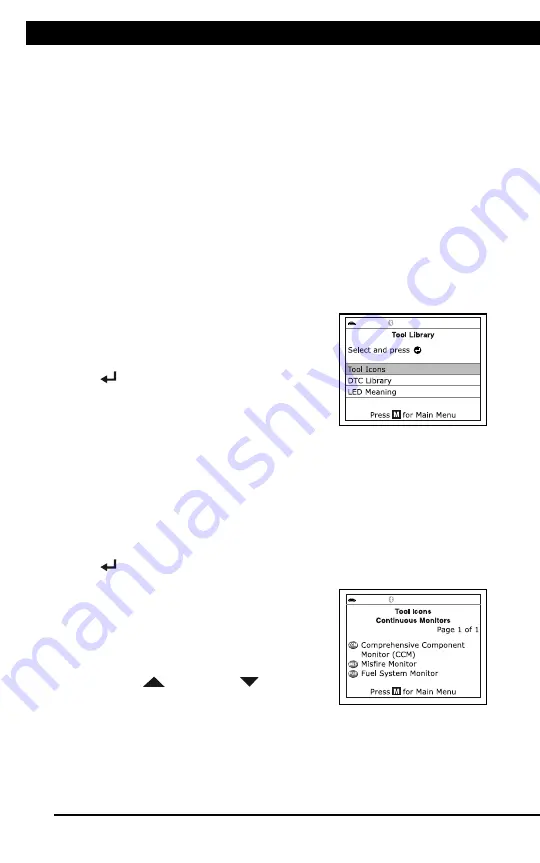
The  Tool  Library  contains  valuable  reference  information  for  the  Scan 

Tool. The following functions are available: 

„


Tool Icons

 – Shows the full names for the 

I/M MONITOR STATUS 

icons  shown  and  descriptions  of  informational  icons  on  the  Scan 

Tool’s display. 

„


DTC Library

 – Provides access library of OBD2 DTC definitions. 

„


LED  Meaning

 – Provides descriptions of the meaning of the Scan 

Tool 

SYSTEM STATUS

 LEDs. 

1. 

While linked to the vehicle, press 

M

„


The Main Menu displays. 

2. 

Select 

Tool Library

, then press 

ENTER


„


The Tool Library menu displays. 

Viewing Tool Icon Descriptions 

The 

I/M  MONITOR  STATUS

  icons  on  the  Scan  Tool’s  LCD  display 

provide an indication of the “Completed / Not Complete” status for all I/M 

Monitors supported by the vehicle under test. The 

Tool  Icons

 function 

displays the full name for each Monitor icon, as well as descriptions of 

the  meanings  of  other  informational  icons  shown  on  the  Scan  Tool’s 

display. 

1. 

From the Tool Library menu, select 

Tool Icons

, then press 

ENTER


„


The Tool Icons screen displays. 

„


The  screen  shows  a  list  of  the  15 
Monitor  icons,  along  with  the  full 
name  for  each  icon,  as  well  as 
descriptions  of  the  meanings  of 
other  informational  icons.  Use  the 

UP


 and 

DOWN


 buttons,  as 

necessary, to scroll the list. 

2. 

When you have finished viewing the tool icon descriptions, press 

M


to return to the Main Menu. 


Содержание ZR13s

Страница 1: ......

Страница 2: ...D T C s a r e p r e s e n t D T C s a r e s h o w n o n t h e S c a n T o o l s L C D d i s p l a y I n t h i s c a s e t h e M a l f u n c t i o n I n d i c a t o r C h e c k E n g i n e l a m p o n...

Страница 3: ...Identifies the I M Monitor status area 4 3 2 5 7 6 1 14 10 11 12 8 9 13 15 IMPORTANT SAFETY INFORMATION About the Scan Tool SAFETY FIRST 1 03257 17 6 7 1 250 7 21 N C O 9P Q 8 RC N C98B 9 7 CM B8 97...

Страница 4: ...i c a t e s t h e r e i s a p r o b l e m i n o n e o r m o r e o f t h e v e h i c l e s s y s t e m s T h e r e d L E D i s a l s o u s e d t o s h o w t h a t D T C s a r e p r e s e n t D T C s a...

Страница 5: ...ly all Monitors on the vehicle are active and performing their diagnostic testing and no DTCs are present 11 YELLOW LED Indicates there is a possible problem A Pending DTC is present and or some of th...

Страница 6: ...i c l e s D a t a L i n k C o n n e c t o r D L C D I S P L A Y F U N C T I O N S F i g u r e 2 D i s p l a y F u n c t i o n s S e e F i g u r e 2 f o r t h e l o c a t i o n s o f i t e m s 1 t h r...

Страница 7: ...ova mobile application please visit www innova com apps for more information A solid blue icon indicates an active Bluetooth connection has been established A solid grey icon indicates Bluetooth is no...

Страница 8: ...p l a y s t e s t r e s u l t s S c a n T o o l f u n c t i o n s a n d M o n i t o r s t a t u s i n f o r m a t i o n S e e D I S P L A Y F U N C T I O N S b e l o w f o r d e t a i l s 1 4 C A B L...

Страница 9: ...ol CODE RETRIEVAL PROCEDURE 7 6 The Scan Tool automatically starts a check of the vehicle s computer to determine which type of communication protocol it is using When the Scan Tool identifies the com...

Страница 10: ...p a n e l w i l l l i g h t s t e a d y o n 1 3 D i s p l a y D i s p l a y s t e s t r e s u l t s S c a n T o o l f u n c t i o n s a n d M o n i t o r s t a t u s i n f o r m a t i o n S e e D I S...

Страница 11: ...5 below 1 I M MONITOR STATUS field Identifies the I M Monitor status area 4 3 2 5 7 6 1 14 10 11 12 8 9 13 15 CODE RETRIEVAL PROCEDURE Using the Scan Tool CODE RETRIEVAL PROCEDURE 9 11 Refer to DISPLA...

Страница 12: ...u n c t i o n s S e e F i g u r e 2 f o r t h e l o c a t i o n s o f i t e m s 1 t h r o u g h 1 5 b e l o w 1 I M M O N I T O R S T A T U S f i e l d I d e n t i f i e s t h e I M M o n i t o r s t...

Страница 13: ...ED DTCs except Ford Mazda 11 THE SYSTEM MENU The System Menu provides the ability to retrieve enhanced DTCs Anti Lock Brake System ABS and Supplemental Restraint System SRS DTCs for most BMW Chrysler...

Страница 14: ...n i t o r s t a t u s i n f o r m a t i o n S e e D I S P L A Y F U N C T I O N S b e l o w f o r d e t a i l s 1 4 C A B L E C o n n e c t s t h e S c a n T o o l t o t h e v e h i c l e s D a t a L...

Страница 15: ...Monitor status area 4 3 2 5 7 6 1 14 10 11 12 8 9 13 15 VIEWING OEM ENHANCED DTCs Using the Scan Tool VIEWING OEM ENHANCED DTCs Ford Mazda only 13 Turn the ignition OFF then back ON Press ENTER Procee...

Страница 16: ...a n e l w i l l l i g h t s t e a d y o n 1 3 D i s p l a y D i s p l a y s t e s t r e s u l t s S c a n T o o l f u n c t i o n s a n d M o n i t o r s t a t u s i n f o r m a t i o n S e e D I S P...

Страница 17: ...eld Identifies the I M Monitor status area 4 3 2 5 7 6 1 14 10 11 12 8 9 13 15 VIEWING SRS DTCs Using the Scan Tool VIEWING SRS DTCs 15 If the definition for the currently displayed code is not availa...

Страница 18: ...u n c t i o n s a n d M o n i t o r s t a t u s i n f o r m a t i o n S e e D I S P L A Y F U N C T I O N S b e l o w f o r d e t a i l s 1 4 C A B L E C o n n e c t s t h e S c a n T o o l t o t h e...

Страница 19: ...from the menu Power on your Code Reader then select from the list of available devices 2 When Bluetooth pairing is complete a confirmation screen displays Click Continue If a Bluetooth connection can...

Страница 20: ...n c t i o n s a n d M o n i t o r s t a t u s i n f o r m a t i o n S e e D I S P L A Y F U N C T I O N S b e l o w f o r d e t a i l s 1 4 C A B L E C o n n e c t s t h e S c a n T o o l t o t h e v...

Страница 21: ...mpare the Live Data PID information displayed on the Scan Tool to specifications in the vehicle s repair manual CUSTOMIZING LIVE DATA PIDs You can customize the Live Data display by placing the Scan T...

Страница 22: ...t a L i n k C o n n e c t o r D L C D I S P L A Y F U N C T I O N S F i g u r e 2 D i s p l a y F u n c t i o n s S e e F i g u r e 2 f o r t h e l o c a t i o n s o f i t e m s 1 t h r o u g h 1 5 b...

Страница 23: ...TOOTH WIFI Using the Scan Tool CONNECTING TO BLUETOOTH WIFI 21 Video Tutorials Watch repair video tutorials for valuable repair tips Technical Service Bulletins Research known problems reported by veh...

Страница 24: ...s t i c t e s t i n g 1 2 R E D L E D I n d i c a t e s t h e r e i s a p r o b l e m i n o n e o r m o r e o f t h e v e h i c l e s s y s t e m s T h e r e d L E D i s a l s o u s e d t o s h o w t...

Страница 25: ...stem status etc generated by the various vehicle sensors switches and actuators These are the same signal values generated by the sensors actuators switches and or vehicle system status information us...

Страница 26: ...i s p l a y s t e s t r e s u l t s S c a n T o o l f u n c t i o n s a n d M o n i t o r s t a t u s i n f o r m a t i o n S e e D I S P L A Y F U N C T I O N S b e l o w f o r d e t a i l s 1 4 C A...

Страница 27: ...vailable Modules then press ENTER 4 When the retrieval process is completed a complete list of modules supported by the vehicle under test displays 5 When you have finished viewing the list of availab...

Страница 28: ...T o o l f u n c t i o n s a n d M o n i t o r s t a t u s i n f o r m a t i o n S e e D I S P L A Y F U N C T I O N S b e l o w f o r d e t a i l s 1 4 C A B L E C o n n e c t s t h e S c a n T o o l...

Страница 29: ...ngine off Repeat for a total of three start stop cycles If the If the scan tool did not detect cranking status for the vehicle s engine an advisory message shows Press ENTER to repeat the battery chec...

Страница 30: ...o r m a t i o n S e e D I S P L A Y F U N C T I O N S b e l o w f o r d e t a i l s 1 4 C A B L E C o n n e c t s t h e S c a n T o o l t o t h e v e h i c l e s D a t a L i n k C o n n e c t o r D L...

Страница 31: ...TOR STATUS field Identifies the I M Monitor status area 4 3 2 5 7 6 1 14 10 11 12 8 9 13 15 LIVE DATA PLAYBACK Live Data Mode LIVE DATA PLAYBACK 29 When you select Yes from the Record Live Data confir...

Страница 32: ...D I S P L A Y F U N C T I O N S F i g u r e 2 D i s p l a y F u n c t i o n s S e e F i g u r e 2 f o r t h e l o c a t i o n s o f i t e m s 1 t h r o u g h 1 5 b e l o w 1 I M M O N I T O R S T A T...

Страница 33: ...10 11 12 8 9 13 15 SYSTEM TEST MENU Additional Tests SYSTEM TEST MENU 31 The Main Menu displays 2 Select System Tests then press ENTER The System Test menu displays If System Tests is not shown on the...

Страница 34: ...o n i t o r s t a t u s i n f o r m a t i o n S e e D I S P L A Y F U N C T I O N S b e l o w f o r d e t a i l s 1 4 C A B L E C o n n e c t s t h e S c a n T o o l t o t h e v e h i c l e s D a t a...

Страница 35: ...gure 2 Display Functions See Figure 2 for the locations of items 1 through 15 below 1 I M MONITOR STATUS field Identifies the I M Monitor status area 4 3 2 5 7 6 1 14 10 11 12 8 9 13 15 RESETTING OIL...

Страница 36: ...n 1 3 D i s p l a y D i s p l a y s t e s t r e s u l t s S c a n T o o l f u n c t i o n s a n d M o n i t o r s t a t u s i n f o r m a t i o n S e e D I S P L A Y F U N C T I O N S b e l o w f o r...

Страница 37: ...elow for details 14 CABLE Connects the Scan Tool to the vehicle s Data Link Connector DLC DISPLAY FUNCTIONS Figure 2 Display Functions See Figure 2 for the locations of items 1 through 15 below 1 I M...

Страница 38: ...n s t r u m e n t p a n e l w i l l l i g h t s t e a d y o n 1 3 D i s p l a y D i s p l a y s t e s t r e s u l t s S c a n T o o l f u n c t i o n s a n d M o n i t o r s t a t u s i n f o r m a t...

Страница 39: ...e 2 for the locations of items 1 through 15 below 1 I M MONITOR STATUS field Identifies the I M Monitor status area 4 3 2 5 7 6 1 14 10 11 12 8 9 13 15 BATTERY ALTERNATOR TEST Additional Tests BATTERY...

Страница 40: ...e l a m p o n t h e v e h i c l e s i n s t r u m e n t p a n e l w i l l l i g h t s t e a d y o n 1 3 D i s p l a y D i s p l a y s t e s t r e s u l t s S c a n T o o l f u n c t i o n s a n d M o...

Страница 41: ...items 1 through 15 below 1 I M MONITOR STATUS field Identifies the I M Monitor status area 4 3 2 5 7 6 1 14 10 11 12 8 9 13 15 VIEWING DRIVE CYCLE PROCEDURES Additional Tests VIEWING TRIP CYCLE PROCED...

Страница 42: ...D i s p l a y D i s p l a y s t e s t r e s u l t s S c a n T o o l f u n c t i o n s a n d M o n i t o r s t a t u s i n f o r m a t i o n S e e D I S P L A Y F U N C T I O N S b e l o w f o r d e t...

Страница 43: ...OR STATUS field Identifies the I M Monitor status area 4 3 2 5 7 6 1 14 10 11 12 8 9 13 15 VIEWING VEHICLE INFORMATION Additional Tests VIEWING VEHICLE INFORMATION 41 VIEWING VEHICLE INFORMATION The V...

Страница 44: ...s u l t s S c a n T o o l f u n c t i o n s a n d M o n i t o r s t a t u s i n f o r m a t i o n S e e D I S P L A Y F U N C T I O N S b e l o w f o r d e t a i l s 1 4 C A B L E C o n n e c t s t h...

Страница 45: ...gure 2 for the locations of items 1 through 15 below 1 I M MONITOR STATUS field Identifies the I M Monitor status area 4 3 2 5 7 6 1 14 10 11 12 8 9 13 15 TOOL LIBRARY Additional Tests THE TOOL LIBRAR...

Страница 46: ...u m e n t p a n e l w i l l l i g h t s t e a d y o n 1 3 D i s p l a y D i s p l a y s t e s t r e s u l t s S c a n T o o l f u n c t i o n s a n d M o n i t o r s t a t u s i n f o r m a t i o n S...

Страница 47: ...NS Figure 2 Display Functions See Figure 2 for the locations of items 1 through 15 below 1 I M MONITOR STATUS field Identifies the I M Monitor status area 4 3 2 5 7 6 1 14 10 11 12 8 9 13 15 ADJUSTMEN...

Страница 48: ...i s p l a y I n t h i s c a s e t h e M a l f u n c t i o n I n d i c a t o r C h e c k E n g i n e l a m p o n t h e v e h i c l e s i n s t r u m e n t p a n e l w i l l l i g h t s t e a d y o n 1...

Страница 49: ...not run their diagnostic testing 12 RED LED Indicates there is a problem in one or more of the vehicle s systems The red LED is also used to show that DTC s are present DTCs are shown on the Scan Too...

Страница 50: ...y o n 1 3 D i s p l a y D i s p l a y s t e s t r e s u l t s S c a n T o o l f u n c t i o n s a n d M o n i t o r s t a t u s i n f o r m a t i o n S e e D I S P L A Y F U N C T I O N S b e l o w f...

Страница 51: ...or status area 4 3 2 5 7 6 1 14 10 11 12 8 9 13 15 90 DAY WARRANTY AND SERVICE PROCEDURES Warranty and Servicing 21 HE DE E WXZC DDL 0D H Y EM __DEC CD H E CZHC WC BEDF AC C ZWXZ b HLWCM HKF F EH WLWC...

Страница 52: ...Distributed by Harbor Freight Tools Calabasas CA 57666 Copyright 2021 All rights reserved Distributed by Harbor Freight Tools Calabasas CA...

Отзывы: