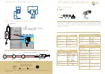
POSITIONING THE CHANNELS
15
NB.
The instructions shown refer to a 7.08 x 3.66 pool refer to page 17. for the measurements for the other pools.
2100
mm
1140
mm
1140
mm
1140
mm
STEP 10.
Once the channels have been assembled and all of the nuts and bolts have been tightened, It’s time to position the assembled
frames into the pool site. Place the first assembled channel across the width of the pool at a point 2100mm from the end of
the cleared area.
NOTE:
2100 Refers to a 3.66m Pool, 2540 refers to a 4.57m pool.
STEP 11.
Place the 2nd and remaining channels at a point 1140mm from the adjacent channel.
NOTE:
1140mm measurements are taken from the centre of the channels
Содержание NOOSA REEF
Страница 10: ...ENLARGED VIEW OF COMPONENTS 8 F2 B2 K C F1 G B1 A2 J D2 E A1 L I...
Страница 22: ...20 Noosa Reef Deep End Excavation Channel Assembly...
Страница 39: ...WALL ASSEMBLY 37 Wall Short Wall Long STEP 27 Control Notch Control Notch...
Страница 45: ...DECK ASSEMBLY 43 7 99m x 4 57m 6 85m x 4 57m LONG TOP DECK LONG TOP DECK...
Страница 56: ...54 Backfill Requirements for Noosa Reef Inground Installation...


