background image

USER MANUAL

USER MANUAL

Step 3:  

Connect the female end of the 12V 

DC power connector from the camera to 
male end on the extension cable.

Step 4:  

 Connect power connector on other 

end of extension cable to Zmodo power 
adapter or power box.

Figure 3-8:  Video/power extension cable and camera's female power 
cable connected

3.2.2 – PTZ (PAN/TILT/ZOOM) CAMERAS

1.  Connect the female BNC video connector from the camera into the male BNC 
video connector of the extension cable.  The male end attaches to the female end 
clockwise and locks into place.  
2.  Your 4-Channel DVR has four video input ports, labeled CH1 to CH4, 
corresponding to the channel that is viewed and configured in the DVR console.  
Select the video input channel of your choice and attach the BNC connector on 
the other end of the extension cable to the video input channel.  See Figure 3-6.
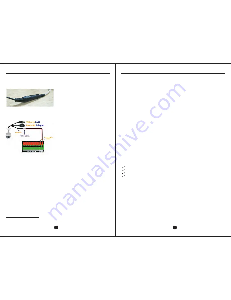
3.  Insert the RS485 wires into the RS485 interface port.
      I. Holding one end of RS485 cable, use wire cutters to strip about ½” of the 
plastic casing around the red and black wires, taking care to not cut or damage 
the copper wire.
      ii. Using a pin or eyeglass screwdriver, depress the tab above the positive (+) 
port.
      iii. Insert the red wire until slight resistance is met.
      iv. Release the tab to lock the wire in place.
      v. Depress the negative (–) tab.
      vi. Insert the black wire until slight resistance is met.
      vii. Release the tab to lock the wire in place.

2

4.   Connect the camera's pink/gray RS485 wires  to the red/black RS485 wires.
      I. Holding the RS485 cable extending from the rear of the camera, use wire

         cutters to strip about ½” of the plastic casing around the pink and gray wires,   
          taking care to not cut or damage the copper wire.
     ii.   Twist the pink and red wires (+) together.  
     iii.  Twist the gray and black wires together (-) together.  
     iv.  Repeat steps i through iii for each additional PTZ camera.
     v.  Secure wires with electrical tape.
5.  Connect the female end of the 12V DC power connector from the camera to 
male end on the extension cable.  See Figure 3-7.
6.  Connect power connector on other end of extension cable to power adapter.  
For instructions on configuring dip switches for PTZ cameras, please visit 
http://zmodo.net or contact Technical Support.

The 9104V package includes a 12V/3A DC power supply.
When connecting the DVR and cameras to a power source, please only use the 
power adapters or power boxes supplied by Zmodo.

Please do not cut, splice, or otherwise modify the electrical wires on any of the 
Zmodo cameras, DVRs, or power supplies.  Doing so will prevent us from 
providing further technical support and will void the equipment warranty.

3.3 – CONNECTING POWER

3.4 – CONNECTING A DISPLAY

3.4.1 – CONNECTING A TV

What you will need:
 

DVR


TV (not included)


BNC to RCA Adapter (sold separately)  


RCA  A/V cable (not included)

Step 1:  Power off DVR and TV.
Step 2:  Locate Video Output port on rear panel of DVR.
Step 3:  Connect BNC-RCA adapter to Video Output port.  (Select Video Output 1   
              as primary output.)  
Step 4:  Insert one end of yellow (video) connector into BNC-RCA adapter and 
              other end into yellow (video) female input jack of TV.
Step 5:  Power on TV.  It may be necessary to change TV channel to AUX or 
              INPUT.
Step 6:  Power on DVR.  Wait until system is fully initialized.

Please refer to Section 2.2 – 9104V Rear Panel for location of ports.

3.4.2 – CONNECTING A COMPUTER MONITOR

What you will need:

1

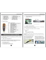
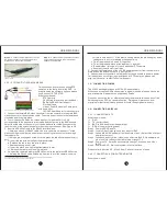
Figure 3-9:  Connecting PTZ camera to RS485 Interface

 1.This figure is only a representation.  Actual RS485 inputs and wire colors may differ slightly.
 2.Camera's RS485 wire colors differ by make and model.

7

8

This section only covers connecting PTZ 
cameras to the rear panel of the DVR.  In 
order to setup the software options, please 
see Section11-PTZ SETUP.
What you will need:
·

PTZ Camera

·

RS485 (red/black) wire (not included)

·

DVR with RS485 interface port

·

Electrical tape

·

Video + Power Extension Cable (sold 

with some kits)
·

12V/5A Power Adapter for each camera

Содержание H9104V

Страница 1: ...H9104V...

Страница 2: ...Display 3 4 1 Connecting a TV 3 4 2 Connecting a Computer Monitor 3 5 Connecting a USB Backup Device 3 6 Connecting a USB Mouse 3 7 Connecting the DVR to a Local Area Network LAN 4 Starting up Your D...

Страница 3: ...hone Setup 28 12 1 User Name 28 12 2 User Password 28 12 3 Server Port 29 12 4 Setting Up Your Phone 29 13 Motion Detection 29 13 1 Options 29 13 2 Motion Detection Area 30 14 System Setup 30 14 1 Tim...

Страница 4: ...and move your videos off site with either a USB flash drive or external hard drive View what you recorded straight from the DVR or remotely from a computer Set up your DVR to be accessed from any Int...

Страница 5: ...Power Supply Built in RS485 Support PELCO P D USB 2 0 USB for Backup USB for mouse Included Included DC12V 3A Table 1 1 DVR Technical Specifications 1 3 PACKAGE CONTENTS 1 9104V DVR 1 12V Power Suppl...

Страница 6: ...amera into the male BNC video connector of the extension cable The male end attaches to the female end clockwise and locks into place Step 2 Your 4 Channel DVR has four video input ports labeled CH1 t...

Страница 7: ...es with electrical tape 5 Connect the female end of the 12V DC power connector from the camera to male end on the extension cable See Figure 3 7 6 Connect power connector on other end of extension cab...

Страница 8: ...he DVR It is the top port labeled with a mouse icon 1 Power off or unplug the DVR 2 Connect mouse 3 Power on or plug in the DVR No other configuration is necessary Troubleshooting Tips Issues There is...

Страница 9: ...igure 5 14 Menu Lock dialog box 5 3 MAIN MENU FUNCTIONS TABLE 5 1 1 Menu Function Buttons The following buttons are common to most menus and submenus DEFAULT Clicking this button resets current menu o...

Страница 10: ...to match PTZ cameras dip switches PTZ Setup Sets a username password and port for connecting to the DVR remotely via mobile phone Mobile Turns and off motion detection Sets sensitivity and detection a...

Страница 11: ...OPTIONS While in Live View Shows or hides current date and time on live video display While Recording Shows or hides date and time while recording 6 6 AUTOSEQ Auto sequencing scrolls through each cha...

Страница 12: ...ay value is the local address of the router to which the DVR is connected The default value is 192 168 1 1 8 7 DNS DNS or Domain Name Server should also be set to the local address of the router 18 17...

Страница 13: ...LOCAL CONNECTION Method 1 Netviewer D9 Client Software 1 Install D9 Viewer on local PC a Software is on CD included in shipment b Download from http zmodo net 2 Launch software 3 Log in to DVR a Enter...

Страница 14: ...ctly See Section 4 3 Setting System Date and Time 2 Enter in a time at which to begin searching for files on the designated date optional 3 Click the Search button to execute the file search 9 2 IDENT...

Страница 15: ...is full At that point it will be necessary to enable overwrite replace the hard drive or format it 10 1 3 HDD FORMAT Clicking this button will execute the hard drive format process Formatting the hard...

Страница 16: ...Output Sets the duration for the external alarm Options are OFF and 10 20 40 or 60 Figure 10 37 Alarm Setup menu seconds Buzzer Sets the duration of the audio buzzer when an alarm condition is met Op...

Страница 17: ...he cameras please see Section 3 2 4 Connecting Your PTZ Cameras For directions on programming the PTZ camera to survey automatically see Section 15 PTZ Cruising The settings under each channel must ma...

Страница 18: ...phone This is not the same password as the admin or user account either for local or Internet access 12 3 SERVER PORT Enter a port over which the mobile phone will communicate with the DVR We recomme...

Страница 19: ...t The user password also grants access to the Quick Launch menu The user password must be six digits and must be different from the admin password After entering the user password type it again in the...

Страница 20: ...he Load Default button will restore all customized settings on the DVR back to their factory defaults It will not erase content on the hard drive Before executing the Load Default process the user wil...

Страница 21: ...A red square with a white H will be displayed on the main video screen if hard drive loss occurs The H icon will also appear if there is no hard drive installed or if it has not been formatted Refer t...

Страница 22: ...iggered Motion may have been detected the hard drive may be low on space or disconnected or a camera may have lost video Check your alarm settings See Section 10 2 17 APPENDICES Zmodo offers its custo...

Отзывы: