background image


INSTRUCTION MANUAL 

Semi-automatic BOV Filling Machine Z-2323 


A0310.02.2323.905.1.EN 

Page 32/39 


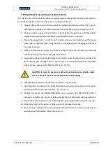
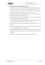
Replacing the lip seal in the filling head 

The lip sealing mounted in filling head is a dynamic seal, therefore it is exposed to wear. Its condition 

should  be  checked  whenever  symptoms  of  head  leakage  are  occurring.  In  order  to  replace  the 

sealing perform following operations: 

1.


Close the inlet of the product to the cylinder by tightening the knurled screw [Fig. 9, pos. 1] 

of the product cylinder non-return valve after loosening the securing nut [Fig. 9, pos. 2]. 

2.


Disable  product  supply  to  the  machine.  It  involves  switching  off  any  installed  product 

pumps and emptying whole installation supplying product to the machine. 

3.


Place empty aerosol container with crimped valve under the filling head. Using footswitch 

START perform single filling cycle on empty container.  

4.


Disable  compressed  air  supply.  It  involves  closing  the  main  cut-off  valve  and  emptying 

whole pneumatic installation supplying the machine. 

5.


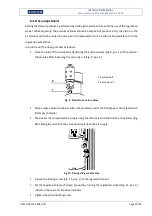
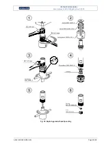
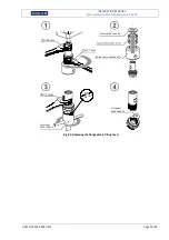
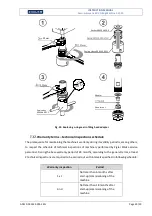
Block the filling head connector using 22 mm flat wrench and unscrew the filling head using 

17 mm flat wrench (insert wrench between spring coils) - Fig. 22, pos. 1. 

6.


Pull gently up and remove the spring, spring mounting washer and covering sleeve - Fig. 22, 

pos. 2. 

7.


Hold the filling head body with  a 17 mm flat wrench and unscrew filling head terminal [Fig. 

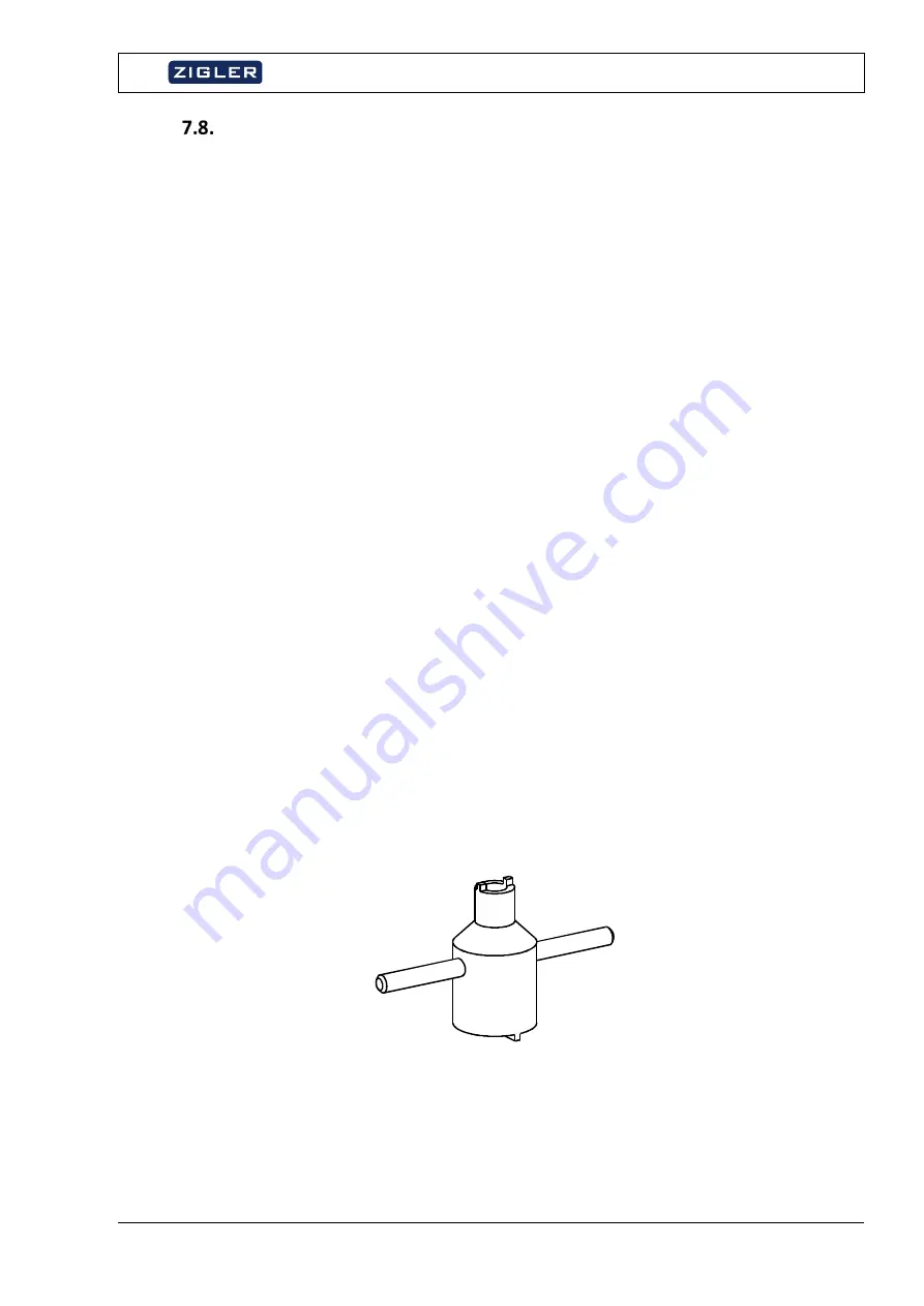
22, pos. 3] using the bigger end of service key [Fig. 21].  

8.


Remove the adapter and the brass sleeve – [Fig. 22, pos. 4]. 

9.


Using the smaller end of service key unscrew the lip seal fitting nut – [Fig. 22, pos. 5]. 

10.


Replace the lip seal 9003.34.000.2 – [Fig. 22, pos. 6]. Before placing the seal, lubricate it 

with pneumatic oil. 

11.


Assemble the filling head parts in the opposite order. 


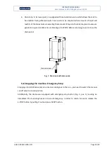
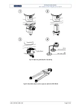
Fig. 21. Service key for filling head (part number 9003.46.001.2)


Содержание Z-2323

Страница 1: ...INSTRUCTIONS 2018 No part of this document may be reprinted or copied by any means without the written permission of ZIGLER POLSKA INSTRUCTION MANUAL Semi automatic BOV Filling Machine Type Z 2323 Signature A0310 02 2323 905 1 EN ...

Страница 2: ...rs and maintenance 10 Protection of the natural environment 10 3 Transport installation and storage of Z 2323 11 Transport 11 Installation 11 Storage 12 4 Construction of Z 2323 Semi automatic BOV Filling Machine 13 Air preparation unit 15 5 Operation manual of Z 2323 17 Steps before starting the machine 17 Starting the machine 17 Stopping the machine Emergency Stop 18 6 Adjustment of operating pa...

Страница 3: ...acing worn out parts 27 Maintenance operations schedule 27 Cleaning instructions 28 Pneumatic oil feeder maintenance 28 Quality of the pneumatic oil 29 Replacing the lip sealing on products piston 30 Replacing the lip seal in the filling head 32 Replacing flat gasket of filling head 34 Replacing the closing Teflon cone of filling head 36 Replacing o ring seal in filling head adapter 38 Warranty te...

Страница 4: ...INSTRUCTION MANUAL Semi automatic BOV Filling Machine Z 2323 A0310 02 2323 905 1 EN Page 4 39 EQUIPMENT MANUFACTURER ...

Страница 5: ...he device is dependent on work organization in the process line Containers diameter φ35 mm φ66 mm Containers height 65 mm 320 mm Overall dimensions and weight Width 560 mm Length 590 mm Height 870 mm Weight 114 kg Supply Type of power supply Compressed air Required air supply pressure 0 8 1 2 MPa 8 12 bar Air consumption 21 liters cycle Air supply connection Pneumatic push in fitting ø12 mm Requir...

Страница 6: ...INSTRUCTION MANUAL Semi automatic BOV Filling Machine Z 2323 A0310 02 2323 905 1 EN Page 6 39 Fig 1 Overall dimensions of Z 2323 ...

Страница 7: ...all warnings warrants and interdiction notes included in this document and placed directly on the machine must be read and observed NOTE Due to the pressure at which the actuators operate it is recommended to preserve caution during operation of the device There is a risk of crushing hands and other body parts in contact with moving machine parts NOTE Dispensed substances may be flammable and fed ...

Страница 8: ...ed by the user to operate the device NOTE This machine has been designed and constructed with a view to use by operators who are not disabled For use by persons with disabilities the device should be adjusted accordingly after prior consultation with the manufacturer Use according to the purpose The purpose of the machine was described in chapter 1 1 Moreover the term use according to the purpose ...

Страница 9: ...rol the condition of compressed air pipes and in case of noticing damage replace any that requires it with the new one 9 All spanners and wrenches as well as other tools serving for regulation of devices tightening screws etc should be removed from the device after completing regulation or assembling works Before starting the device again check whether this has really been done 10 Operating the Fi...

Страница 10: ... works lower the pressure of the air supplied to the device to the atmospheric level Protection of the natural environment Damaged containers should be stored in an appointed place in order to be handed over for recycling Damaged containers may not be disposed of into waste containers Any possible leaks of active substances should be washed down and remaining liquid waste directed into proper tank...

Страница 11: ...on depending on the table height After the initial placing the machine on destination site provide compressed air supply to the connection at the right side panel of the cabinet Fig 2 pos 1 Proper connection requires providing of a pneumatic tube of ext diameter ø12 mm Furthermore due to the use of oiled compressed air in machine all exhausts of air discharged from valves were collected in one cir...

Страница 12: ...It is thus recommended to build in the filter before the inlet of the machine It is absolutely necessary to prevent entering by external solid particles capable of causing damage to filling instruments Brand new machines may bear the traces of oil Before starting actual use it is recommended to fill several containers with a product in order to rinse the filling instruments Containers filled this ...

Страница 13: ...ng system 4 START footswitch initiating cycle 14 Vacuum generator 5 EMERGENCY STOP button 15 Vacuum unit logic pressure gauge 6 RESET button restoring power after E Stop 16 Vacuum unit logic pressure regulator 7 Liquid product supply connection G BSP 17 Cleaning head lowering pressure gauge 8 Product dosing unit described below 18 Cleaning head lowering pressure regulator 9 Filling head 19 Filling...

Страница 14: ...heel 2 Dose indicator 3 Air cylinder 4 Product cylinder 5 Cylinders connector 6 Product non return valve 7 Locking screw of regulation wheel 8 Limit switch of dispensing move 9 Throttling valve to control filling rate 10 Slide valve to cut off air supply to the air cylinder 11 Product inlet from tank or pump 12 Product outlet to filling head Fig 4 Product dosing unit 11 4 8 3 7 10 9 6 5 1 2 12 ...

Страница 15: ...put pressure set on the control valve is indicated by the control pressure gauge Compressed air filter purify air collected from installation from small solid particles and droplets of moistness Particles bigger than 40 µm depending on filter cartridge are stopped by sintered filter and liquid substances are stopped by special devices separated from filter container Condensate gathering in filter ...

Страница 16: ... draining screw Fig 5 Construction of air preparation unit Condensate in the filter container should be checked daily and removed if necessary The above description relates to the air preparation unit manufactured by FESTO In manufactured by ZIGLER POLSKA products there are air preparation units from the following producers FESTO CAMOZZI SMC CKD METALWORK Principle of operation and construction of...

Страница 17: ...imiters is appropriate for the diameter of container If necessary adjust it in accordance with chapter 6 4 Starting the machine Properly installed machine should be operated only by appropriately qualified personnel in accordance with chapter 2 2 First place the aerosol container centrally in the axis of the filling head correct positioning should be set with the limiters in accordance with chapte...

Страница 18: ...acuum generation system malfunction or blockage CAUTION Before returning to work close the drain valve Fig 7 Drain tank with drain valve Stopping the machine Emergency Stop Stopping of a Z 2323 takes place in a manner analogous to the run you need to switch the manual cut off valve to closed position Additionally the device was equipped with emergency stop button Fig 3 pos 5 causing an immediate l...

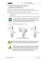
Страница 19: ...e until the desired pressure appear on the pressure gauge The desired pressure value should always be reached from the bottom namely by increment E g to decrease the operating pressure from 6 bar to 3 bar first lower the pressure to 2 bar and then raise it to 3 bar 3 Lock control knob by gently pushing down it clicks Fig 8 Adjustment of operating pressure NOTE When adjusting the working pressure o...

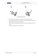
Страница 20: ...t by tightening the knurled screw Fig 9 pos 1 of the product check valve after loosening the securing nut Fig 9 pos 2 1 Knurled bolt 2 Securing nut Fig 9 Product non return valve Place empty aerosol container with crimped valve under the Filling head Using footswitch fill empty container Disconnect the compressed air supply using the slide valve installed on the air cylinder Fig 10 Sliding the swi...

Страница 21: ...air supply by moving the slide valve up to opened position Open the inflow of the product to the product cylinder by unscrewing the knurled screw and gently tighten the securing nut on check valve Conduct 5 trial cycles of filling checking the precision of dosing by weighting or by volume control If necessary adjust the amount of dosed product ...

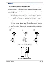
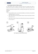
Страница 22: ... the side in upper part of the stand Fig 12 pos 1 2 Raise the Filling head by turning the crank clockwise Fig 12 pos 1 to such a height that the gap between the aerosol valve stem tube and the Filling head is 5 7 mm Fig 13 3 Using a footswitch fill one container If the lowering actuator returns instantly to its initial upper position without filling the container the gap is too large Reduce the he...

Страница 23: ...e regulation of the location of limiters consists in ensuring the axial setting of the container and the Filling head Setting Using hex Allen key size 5 mm loosen blocking M6 screws on limiters and move limiters completely backwards Fig 14 pos 1 Place a bottle directly under crimping head and check coaxiality of the aerosol can and the head Fig 14 pos 2 Move limiters directly to the aerosol can an...

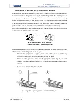
Страница 24: ...h is located too far won t detect it Correct sensors placement may be checked by observing pneumatic indicator on sensor Protruded indicator means that limit position is detected Fig 15 Magnetic proximity sensor SMPO type a indicator hidden back b indicator protruded Compressed air supply has to be turned on during proximity sensors regulation To adjust position of sensor in square actuator groove...

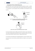
Страница 25: ...e mounted on actuator a with socket for screwdriver b with thumb bolt Fig 18 Non return flow control valve GR type mounted on cables In case of one way flow control valve GRLA type with socket for screwdriver Fig 17 a regulation is conducted by turning regulation bolt using flat screwdriver in appropriate direction To slow down actuator movement speed or extend time delay turn regulation bolt cloc...

Страница 26: ...minate these influences every pneumatic control system must be equipped with devices preparing compressed air Air must always be so clean that it could not cause any disturbances or damage Because every filter causes resistance to flow as well compressedair should be from the economy point of view always only as clean as it is necessary The quality of compressed air is described with accuracy clas...

Страница 27: ...t thoroughly in kerosene or proper solvent Self sealing rings and seals should never be mounted dry Before fitting they must always be moistened with pneumatic oil Maintenance operations schedule 1 Air preparation unit check the quality of oil and fill it up check the amount of oil dosed into pneumatic systems once a week 2 Water level in the air filter check every day do not allow the water to re...

Страница 28: ...er to do so Switch cut off valve to the open position using the screwdriver turn the adjustment screw a left counter clockwise to increase the dose b right clockwise to reduce the dose Settings can be checked through a transparent eyehole in the dome with the adjustment screw In order to ensure proper working conditions the lubrication setting should be at 1 DROP 500 WORK CYCLES After having been ...

Страница 29: ...proper pneumatic oils available on the market and a regular supplier of oil will make all information available in case of any doubts Complex oils emitting graphite soap etc are not recommended to be used with mini head lubricants Certain special lubricating agents particularly synthetic may contain compounds which are not compatible with O rings seals or other kinds of equipment The manufacturer ...

Страница 30: ... valve and emptying whole pneumatic installation supplying the machine 5 Unscrew the knurled nut while holding the cylinder connecting the product cylinder with the remaining part of filling module Fig 19 pos 1 To facilitate the task use adjustable caliper pin face spanner pin diameter ø5 5 mm Fig 20 CAUTION In order to preserve safety during maintenance activities make sure that product cylinder ...

Страница 31: ...matic BOV Filling Machine Z 2323 A0310 02 2323 905 1 EN Page 31 39 Fig 19 Replacing product piston lip sealing Fig 20 Adjustable caliper pin face spanner similar to DIN 3116A Sealing 9003 42 001 0 VS1 Ring 9003 42 001 0 GR1 19 mm ...

Страница 32: ...Using footswitch START perform single filling cycle on empty container 4 Disable compressed air supply It involves closing the main cut off valve and emptying whole pneumatic installation supplying the machine 5 Block the filling head connector using 22 mm flat wrench and unscrew the filling head using 17 mm flat wrench insert wrench between spring coils Fig 22 pos 1 6 Pull gently up and remove th...

Страница 33: ... 02 2323 905 1 EN Page 33 39 Fig 22 Replacing product head lip sealing Sealing 9003 34 000 2 VS1 Nut 9003 34 636 0 17 mm Service key 9003 46 001 2 22 mm 17 mm Adapter Brass sleeve 9003 34 612 0 Gasket 9003 34 650 0 Spring 9003 34 005 1 SG2 Sealing sleeve 9003 34 651 1 ...

Страница 34: ...ontainer with crimped valve under the filling head Using footswitch START perform single filling cycle on empty container 4 Disable compressed air supply It involves closing the main cut off valve and emptying whole pneumatic installation supplying the machine 5 Block the filling head connector using 22 mm flat wrench and unscrew the filling head using 17 mm flat wrench insert wrench between sprin...

Страница 35: ...ng Machine Z 2323 A0310 02 2323 905 1 EN Page 35 39 Fig 23 Replacing the flat gasket in filling head Flat gasket 9003 34 607 0 17 mm Service key 9003 46 001 2 22 mm 17 mm Gasket 9003 34 650 0 Spring 9003 34 005 1 SG2 Sealing sleeve 9003 34 651 1 ...

Страница 36: ...ve under the filling head Using footswitch START perform single filling cycle on empty container 4 Disable compressed air supply It involves closing the main cut off valve and emptying whole pneumatic installation supplying the machine 5 Block the filling head connector using 22 mm flat wrench and unscrew the filling head using 17 mm flat wrench insert wrench between spring coils Fig 24 pos 1 6 Pu...

Страница 37: ...chine Z 2323 A0310 02 2323 905 1 EN Page 37 39 Fig 24 Replacing filling head Teflon cone Nut 9003 34 634 1 Teflon cone 9003 34 002 0 17 mm 5 mm 22 mm Spring 9003 34 000 2 SG1 Gasket 9003 34 650 0 Spring 9003 34 005 1 SG2 Sealing sleeve 9003 34 651 1 ...

Страница 38: ...tainer 4 Disable compressed air supply It involves closing the main cut off valve and emptying whole pneumatic installation supplying the machine 5 Block the filling head connector using 22 mm flat wrench and unscrew the filling head using 17 mm flat wrench insert wrench between spring coils Fig 25 pos 1 6 Pull gently up and remove the spring spring mounting washer and covering sleeve Fig 25 pos 2...

Страница 39: ...performed by Zigler Polska service personnel During the base warranty period of 24 months according to the general terms at least 2 technical inspections are required to be carried out with intervals specified in following schedule Warranty inspection Period 1 st Not later than 6 months after start up commissioning of the machine 2 nd Not later than 18 months after start up commissioning of the ma...

Страница 40: ... Directive 20IA 34 EU obtained throughcompliance with thefollowing harmonized standards PN ENL3453 t 2OtO PN ENt1 27 t 2OLt PN EN 15198 2009 Thisdeclaration of conformity is the basis for marking the product with r C signandan explosion safe category designation rx tt2GilBT4Gb 2 csTas60 c 13 09 20L8 Jaworzno dateandlocation TechnicaI Documentoti on SpecioIist Thisdeclaration is void if Userdoesnot...

Страница 41: ...r social unrest unforeseen accidents and normal wear and tear c equipment in which any person other than the AGENT s authorised service staff including the PRINCIPAL interfered in any way or made any changes or modifications to the equipment d equipment where serial numbers have been removed or erased in any way whatsoever e sealing clamping jaws clamping jaw expansion pin V belts safety housing g...

Страница 42: ...PNEUMATIC DIAGRAMS ...

Страница 43: ... 1V22 2 1 2 1W3 6 bar 6 bar 6 bar Product 1 1Z3 1V12 2 1 3 12 1B1 1V29 1V14 2 1 3 12 1V26 2 1 1V13 2 1 3 12 14 1A2 1V15 2 1 1 1V23 2 1 1V21 2 3 1 1 1Z1 2 1V11 2 1 1 1X1 1 2 3 V00 Exhaust A B C D ZIGLER Polska Sp z o o ul Braci Gutmanów 7 43 600 Jaworzno POLSKA Revision Designed by Draw by Subtype 2018 08 31 Dawid Mroczek Project No Device No Device name Device type Document No Page name Page No Co...

Страница 44: ...SPARE PARTS LIST WITH TECHNICAL DRAWINGS ...

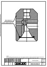
Страница 45: ...by Designed by Date A4 Checked by P Horbaczewski P Horbaczewski 0 824 kg 2017 05 18 2017 05 18 2017 05 18 1 2017 05 18 NOTE When ordering spare parts make sure to use drawing number as well as exact symbol marking of particular part Only complete information will allow to identify the part and properly process your order 2323 00 601 1 2323 00 002 0 OR1 ...

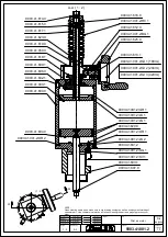
Страница 46: ... SG 1 9003 41 604 0 9003 41 001 2 LS 1 9003 41 001 2 GR 1 9003 41 000 1 9003 41 600 0 9003 41 602 1 9003 41 608 0 9003 41 609 1 9003 41 618 1 9003 41 050 0 9003 41 619 0 9003 41 001 2 GI 1 188ml 9003 41 001 2 GI 2 294ml 9003 41 001 2 GI 3 420ml 9003 41 623 0 9003 41 001 2 BG 1 9003 41 612 0 9003 41 001 2 RC 1 9003 41 613 1 9003 41 617 1 9003 41 615 0 9003 41 614 0 9003 41 001 2 OR 1 NOTE When orde...

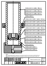
Страница 47: ... 42 609 2 50 294 ml 9003 42 608 3 60 420 ml 9003 42 612 1 40 188 ml 9003 42 611 1 50 294 ml 9003 42 613 1 60 420 ml 9003 42 600 1 9003 42 001 0 OR 2 9003 42 001 0 GR 1 40 188 ml 9003 42 001 0 GR 2 50 294 ml 9003 42 001 0 GR 3 60 420 ml 9003 42 001 0 VS 1 40 188 ml 9003 42 001 0 VS 2 50 294 ml 9003 42 001 0 VS 3 60 420 ml 9001 42 618 1 NOTE When ordering spare parts make sure to use drawing number ...

Страница 48: ...baczewski 12 852 kg 2018 05 11 2018 05 11 2018 05 11 1 2018 05 11 833 9019 01 602 0 9019 05 613 0 NOTE When ordering spare parts make sure to use drawing number as well as exact symbol marking of particular part Only complete information will allow to identify the part and properly process your order 9019 00 002 1 AH1 9019 00 002 1 HW1 9019 01 050 0 9019 05 617 1 9019 05 615 0 9019 01 602 0 9019 0...

Страница 49: ... 00 610 0 9026 00 613 0 9026 00 001 0 OR1 9026 00 001 0 LS1 9026 00 612 1 9026 00 001 0 OR2 9026 00 001 0 OR3 9026 00 001 0 VS1 9026 00 611 0 9026 00 001 0 BL1 9026 00 616 0 9025 00 605 2 9026 00 001 0 OR4 9026 00 001 0 RR1 9026 00 615 0 9026 00 607 2 9026 00 618 0 9026 00 001 0 OR5 NOTE When ordering spare parts make sure to use drawing number as well as exact symbol marking of particular part On...

Страница 50: ...2 OR2 9003 34 002 0 9003 34 633 0 9003 34 000 2 SG1 9003 34 636 0 9003 34 634 1 9003 34 000 2 OR1 9003 34 639 0 9003 34 632 1 9003 34 628 0 d2 12 9003 34 639 0 d2 14 NOTE When ordering spare parts make sure to use drawing number as well as exact symbol marking of particular part Only complete information will allow to identify the part and properly process your order 9003 34 000 2 VS1 9003 34 652 ...

Отзывы: