background image


PULSAR

®

 PLUS III-S, III-S6, and VI-S SUCTION BLAST CABINETS 

Page 14


© 2021 CLEMCO INDUSTRIES CORP.  

  www.clemcoindustries.com  

  Manual No. 30421 

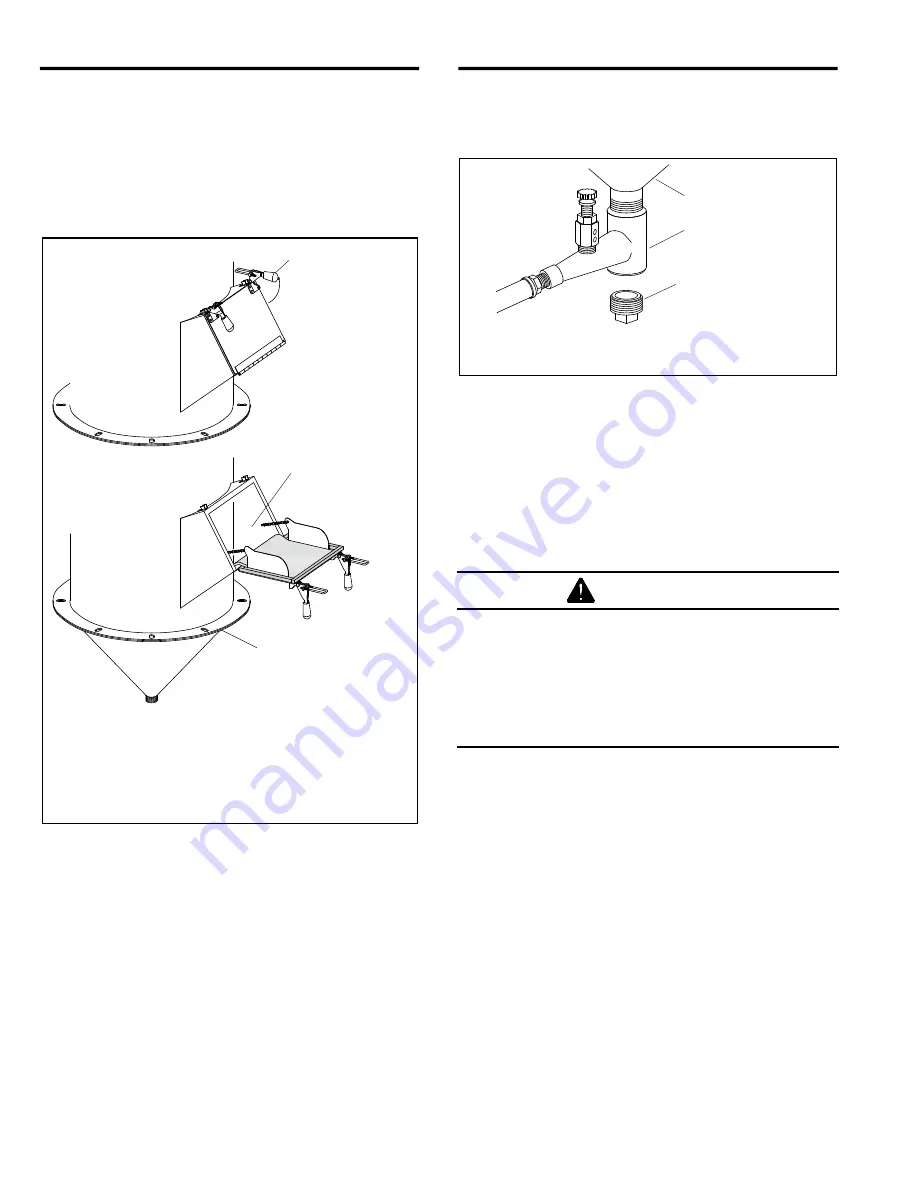
1.  Turn OFF the exhauster.  


2.  Unhook the two door latches and open the reclaimer 

fill door. 


3.  Add  clean,  dry  media  by  pouring  it  through  the  door 

opening.  Do  not  fill  above  the  reclaimer  cone,  as 
shown in Figure 12.  


Pulsar VI reclaimer shown. Pulsar III reclaimer is 
slightly  different,  the  door  does  not  include  a 
chain, but functions the same. 


Figure 12 


4.3 

Media Unloading


‒ Figure 13 


4.3.1

  To empty the cabinet and reclaimer of media: 

1.  Use  the  blow-off  nozzle  to  blow  off  the  cabinet 

interior  and  run  the  exhauster  until  all  media  is 
recovered from the cabinet.  


2.  Turn OFF the exhauster and place an empty bucket 

or other suitable container under the metering valve. 


3.  Unscrew  the  plastic  drain  plug  from  the  metering 

valve,  permitting  media  to  flow  into  the  bucket.  If 
media does not flow, it has caked; open the fill door 
and stir media until it starts to flow.  


4.  Before  the  container  becomes  too  heavy  to  easily 

manage, replace the plug and empty the container. 


5.  Replace the plug when the reclaimer is empty, or, if 

changing  media  type,  purge  the  media  hose,  as 
noted below.  


Figure 13 


4.3.2

  To  purge  the  media  hose,  before  replacing  the 

plug  turn  ON  the  exhauster,  grasp  the  gun,  and  press 
the  foot  pedal  using  the  gun  to  blow  off  the  cabinet 
interior  until  the  air  from  the  gun  and  the  cabinet  are 
clear. Turn OFF the exhauster and replace the plug. 


4.4 

Loading and Unloading Parts




Use solid fixturing to hold heavy parts in place. 
Do not remove lift equipment until the part is 
adequately supported to prevent movement. 
Moving heavy, unsupported parts may cause 
them to shift or topple, and cause severe injury. 
This is especially important with the use of 
turntables.


NOTE:  Parts  must  be  free  of  oil,  water,  grease,  or 
other contaminants that will clump media or clog the 
filter cartridge.

 If parts are oily or greasy, degrease and 

dry them prior to blasting. 

 
4.4.1

  Load and unload parts through either door. 


4.4.2 

When  blasting  small  parts  or  objects  having 

small  pieces  that  could  become  dislodged  and  fall  off, 
place  an  appropriately  sized  screen  over  the  grate  (or 
under the grate  when frequently blasting small parts) to 
prevent  parts  from  falling  into  the  hopper.  If  an  object 
should  fall  through  the  grate,  stop  blasting  immediately 
and retrieve it. 
 

4.4.3 

Close  door;  the  door  interlock  system  prevents 

blasting if either door is open. 


Reclaimer Hopper 

Metering Valve 

Plastic Drain Plug 

Unscrew plug to empty 
media from reclaimer. 

Do not fill above the 
reclaimer cone. 

Load media by 
pouring it through 
the fill door. 

Swing the door 
latch handles up 
to unhook the 
latches. 

Open the 
reclaimer fill door. 

Содержание Pulsar Plus lll-S

Страница 1: ...oduction rate or useful life of these products All estimates regarding production rates or finishes are the responsibility of the user and must be derived solely from the user s experience and experti...

Страница 2: ...es a hazardous situation that if not avoided could result in minor or moderate injury Warning indicates a hazardous situation that if not avoided could result in death or serious injury Danger indicat...

Страница 3: ...7 15 Clean Dust Collector s Inline Filter 7 16 Clean Dust Collector s Snubber Fittings 7 17 Diaphragm Pulse Valve 7 18 TROUBLESHOOTING PNEU and MECHANICAL 8 0 Poor visibility dusty media 8 1 Abnormall...

Страница 4: ...cords and hoses Power Lift Leg Assembly Lifting Eye Reclaimer Power Module Dust Collector Reclaimer Inlet Flex Hose Between cabinet hopper and reclaimer inlet Arrows show directions of air flow Forkli...

Страница 5: ...inst the inner surface of the cartridge The expanding air momentarily reverses air flow through the cartridge releasing dust accumulated on the outer surface The dust particles fall away from the cart...

Страница 6: ...toxic coatings heavy metals or any other toxic materials HEPA filter is listed in Section 10 1 Optional Accessories All dust is hazardous to breath Emissions can occur from the dust collection system...

Страница 7: ...which includes rubber curtains for the cabinet interior and a boron carbide lined nozzle When using aggressive media on a regular basis install the aluminum oxide kit and a fully rubber lined reclaime...

Страница 8: ...ly important in areas of high humidity or when fine mesh media are used Moisture causes media to clump and inhibits free flow through the feed assembly If the filter does not remove enough moisture to...

Страница 9: ...Blast Pressure Gauge Blast Pressure Pilot Regulator Red Pushbutton STOP Switch BNP Blast Gun Glove Ports Lift Leg Foot Pads 4 Control Tubing from Power Module as shown in Figure 7 Male Power Cord Con...

Страница 10: ...fer to Figure 7 Control Tubing as shown in Figure 7 Filter Cartridge Dustbin Shown removed from under dust collector Flex Hose To cabinet hopper as shown in Figure 5 Blow Off Hose refer to Figure 5 Me...

Страница 11: ...tion for service Once the valve is installed turn it off and perform lockout and tagout procedure until all air connections are done To avoid the risk of injury from compressed air install an isolatio...

Страница 12: ...power module 2 5 Connect Electrical Service Shorting electrical components can result in serious injury or death from electrical shock or equipment damage Electrical power must be locked out and tagg...

Страница 13: ...se The wire has been stripped on hoses supplied on new cabinets Use care not to damage the hose Clamp flex hose securely in position with worm clamps provided NOTE The hose wire helps dissipate static...

Страница 14: ...washer is used between the screw head and the rubber curtain grommet on all curtains 3 2 3 Doors Using protectors against the curtains and outer doors clamp the door curtains in place NOTE When layin...

Страница 15: ...he plug turn ON the exhauster grasp the gun and press the foot pedal using the gun to blow off the cabinet interior until the air from the gun and the cabinet are clear Turn OFF the exhauster and repl...

Страница 16: ...ins immediately Shut down the cabinet immediately if dust discharges from the dust collector or cabinet Check to make sure the dust collector filter cartridge is correctly seated and that it is not wo...

Страница 17: ...knob by pulling it out as shown in Figure 14 and turn it clockwise to increase pressure or counterclockwise to decrease pressure Pressure may drop slightly from closed line pressure when blasting star...

Страница 18: ...essure gauge is useful for adjusting and monitoring static pressure The manometer kit and differential pressure gauge are listed in Section 10 1 Optional Accessories Refer to Section 5 11 for using th...

Страница 19: ...blasting when the doors are closed 5 7 Dustbin Interlock Figure 19 5 7 1 The dustbin interlock switch disables blasting when the dustbin is lowered to remove it from under the dust collector 5 7 2 To...

Страница 20: ...20 Turn the knob clockwise to increase pressure or counterclockwise to decrease pressure Once operating pressure is set push down on the knob to secure it and maintain the setting Some Items removed...

Страница 21: ...cidentally changed refer to Section 5 9 5 to reset them to factory settings 5 9 1 1 The LED display comes on the green start pushbutton is pressed and power is supplied to the timer TEST o f f o n on...

Страница 22: ...ow up button until 15 appears When 15 appears on the display do not press anything after a few seconds the display starts flashing indicating the new time is being saved Once the new time is saved the...

Страница 23: ...osure Do not confuse cabinet static pressure with reclaimer static pressure which is controlled by the exhaust damper as noted in Section 5 4 Reclaimer pressure must be set before cabinet pressure 5 1...

Страница 24: ...eter and install the fitting into the coupling as shown in Figure 28 5 11 7 2 Place the unused end of the manometer tubing over only the first tapered barb on the barb fitting pushing the tubing all t...

Страница 25: ...tion schedule Inspect all parts subjected to media contact including the gun and nozzle media hose flex hose wear plate and all items covered in this section Adjust the inspection schedule as needed b...

Страница 26: ...nspect cabinet door seals for media leaks Dust leaking from the inlet damper or other places on the cabinet indicates a saturated filter cartridge Refer to Section 6 7 for additional pulsing 6 3 2 Che...

Страница 27: ...dust to clear and then repeat the process as needed 7 0 SERVICE MAINTENANCE Prior to doing any maintenance or opening the dust collector the employer must meet required OSHA standards including but no...

Страница 28: ...nsert both gloves through both glove ports 7 2 6 Align the slots in the glove mount with the shoulder screw heads on the attachment ring push in on the glove mount and then turn it clockwise to lock i...

Страница 29: ...lace it per section 7 6 7 5 4 Install a view window cover lens per Section 7 4 7 5 5 Set the new window cover lens down squarely over the window opening making sure that all edges of the window are ce...

Страница 30: ...he cabinet lift the light off the diffuser as shown in Figure 36 Set the light out of the way and within reach of the cord Figure 36 7 8 2 Diffuser lens replacement 7 8 2 1 Remove the light assembly a...

Страница 31: ...7 9 1 To remove the tubing push the retaining collar toward the fitting which releases the tubing so it can be easily removed by pulling it out Do not force it only a slight pull on the tubing is req...

Страница 32: ...fm reclaimer with welded on nonremovable top Figure 40 Refer to Section 7 11 2 to replace the wear plate in a 600 cfm reclaimer with a bolt on removable top Installation Notes Make sure an inlet pipe...

Страница 33: ...allation Notes The Pulsar VI wear plate may be replaced by using the method described in Section 7 11 1 or from the top as explained in this section If the top is removed make sure at least 6 feet of...

Страница 34: ...ailable 7 12 1 Remove the flex hoses from the reclaimer inlet and outlet and then remove the inlet pipe adaptor 7 12 2 Make a note of the reclaimer s alignment the reclaimer door is facing the power m...

Страница 35: ...instructions provided with the adhesive some adhesives need to be applied to both contact surfaces Apply a multipurpose contact adhesive such as 3M No 10 neoprene contact adhesive or equal to the fab...

Страница 36: ...t in alignment 7 12 24 9th Place the cylinder liner over the inner tube Make sure the liner is tight against the top liner and use worm clamps to temporarily clamp the liner to the tube Tack weld the...

Страница 37: ...caulk to the seam opposite side of the mounting bolts between the baffle and reclaimer body Wipe the caulk smooth 7 13 7 Inspect the strip gasket on the reclaimer upper flange replace it if damaged or...

Страница 38: ...compressed or otherwise damaged 7 14 10 Hang the door on the support angle align the hole with the mounting stud and install the knob and tighten it securely 7 14 11 Season the cartridge per Section 7...

Страница 39: ...er if the element or body is damaged or otherwise faulty 5 Place the filter onto the bottom cap and insert the bottom cap into the filter body Rotate the bottom cap while gently pushing it upward unti...

Страница 40: ...left of the diaphragm as shown in Figure 54 When reinstalling the diaphragm the marks must be aligned as shown Figure 54 7 18 3 Reassemble using the new diaphragm and O ring from the service kit makin...

Страница 41: ...n Check door 8 1 8 Hole worn in flex hose between cabinet hopper and reclaimer inlet or reclaimer outlet and dust collector inlet Replace hose 8 1 9 Obstruction in flex hose between the cabinet hopper...

Страница 42: ...r may require the installation of an air dryer or aftercooler in the air supply line 8 5 4 Absorption Some media types tend to absorb moisture from the air especially fine mesh media in areas of high...

Страница 43: ...ulator 8 13 Media buildup in cabinet hopper media does not convey to reclaimer NOTE Do not pour media directly into the cabinet hopper as overfilling may occur Overfilling results in media carryover t...

Страница 44: ...e switch is pressed 2 Make sure the power cord is connected and that power is supplied to the outlet 3 If the display is not lit after checking the above have the electrical system checked by a qualif...

Страница 45: ...witch is bad 9 1 4 1 With the dust collector bin locked in place correctly check voltage between Terminals 10 and 2 If 120 VAC is not present dust collector bin switch has an issue Check wiring and me...

Страница 46: ...open If 120 VAC is not present with the door closed the switch has an issue Check wiring and switch 9 4 1 3 With dust collector motor on and running and the left hand door closed check right hand door...

Страница 47: ...or front of cab 24744 Window cover lens pack of 5 06190 Differential pressure gauge assembly for measuring reclaimer static pressure 23355 Aluminum oxide kits For cabinets using aggressive media The k...

Страница 48: ...et side liner 29532 6 Cone liner 29707 7 Inlet top liner 29536 8 Screw 10 16 x 3 4 self drill tap 12722 Figure 57 Optional Extension Nozzles Figure 58 Item Description Stock No 1 3 Straight extension...

Страница 49: ...se 3 4 ID 11798 8 Door latch assembly 20064 9 Foot pedal electric 30188 10 Gasket 5 32 x 3 4 3 ft required 00192 11 Detent sleeve door interlock 15042 12 Bracket door interlock actuator 19152 13 Clamp...

Страница 50: ...h lock el 1 4 x 1 4 tube 30373 10 Reducing union 1 4 x 5 16 tubing 30372 11 Switch 3 position selector 30293 12 Switch green LED pushbutton 30291 13 Switch red pushbutton 30292 14 Washer color code Wh...

Страница 51: ...ring valve 12011 Figure 62 10 6 Gloves and Glove Attachments Figure 63 Item Description Stock No A Armrest glove mount kit each includes items 1 thru 5 10 and 11 30192 B Mounting ring kit glove mount...

Страница 52: ...75 3 Gun body 11802 4 Lock nut air jet 11913 5 Elastic jet sleeve 12097 6 Air jet assembly w Item 5 No 4 12342 No 5 12343 No 6 12344 No 7 12345 No 8 12346 7 Fitting hose 3 8 NPT x 1 2 barb 06369 8 Hos...

Страница 53: ...PT 06369 19 Blow off nozzle 13116 20 Air hose 1 2 ID specify feet required 12472 21 Gun assembly BNP No 5 standard Refer to Section 10 8 for other sizes 12302 22 Hose media 1 2 ID clear urethane speci...

Страница 54: ...embly Pulsar VI Includes items with an asterisk 30462 1 Inlet pipe adaptor 4 for use with steel media 30496 5 standard use other than steel 29397 2 Gasket inlet pipe adaptor for standard and steel med...

Страница 55: ...15 Nipple 1 4 brass hex 02808 16 Gasket exhaust damper for 300 cfm 30198 for 600 cfm 30240 17 Clamp J hook dustbin 30190 18 Knob dust door retainer 30191 19 Clamp 6 hose 00750 20 Hose 6 unlined flex 4...

Отзывы: