


Note: For naming purposes only, the lower sockets are referred to
as bank 4 later in this chapter.
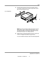
3.
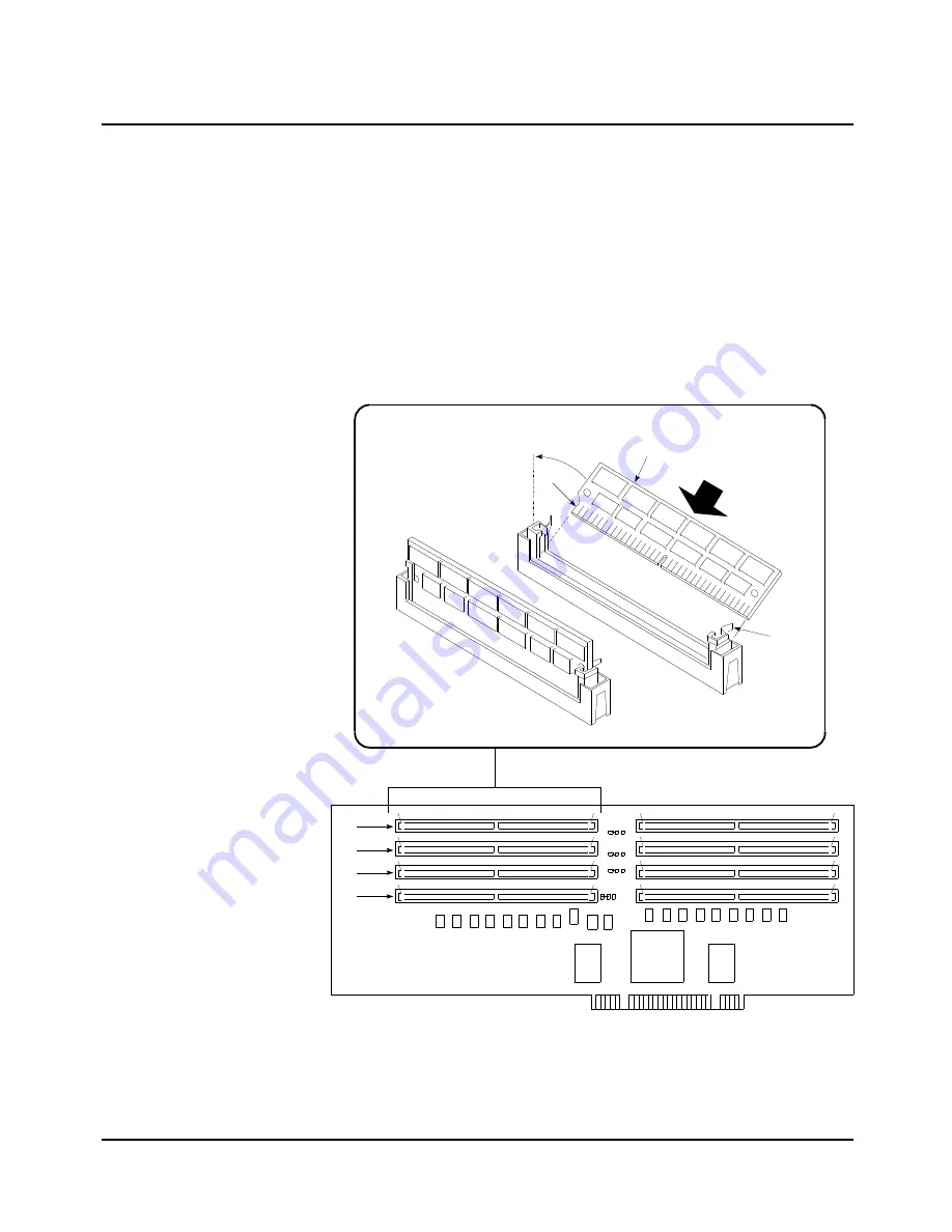
Holding the SIMM module only by the edges, remove it from
its antistatic package.
4.
With the notched edge (A) of the SIMM facing towards the
left edge of the module, position the SIMM (B) at a 45 angle
relative to the socket on the board and insert the bottom edge
of the SIMM into the socket. Press down firmly on the SIMM
until it seats correctly.
(F4-13 54840007)
B
C
A
D
C
B
A
04/APRIL/93 – 595-5484-UU
76
4-22
Upgrades and Options


