


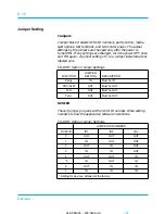
J7 PINS
DEFAULT
DESCRIPTION
1-2
IN
Parity
IN = Enabled
OUT = Disabled
3-4
IN
Remote start
IN = Enabled
OUT = Disabled
J8 PINS
DEFAULT
DESCRIPTION
3
Out
Removed for key
9
Out
Clock ground
10
Out
External spindle clock sync
13
Out
Remote LED -
14
Out
Remote LED +
NOTE
All other pins are reserved. (no jumpers are installed)
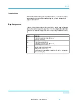
J5 PINS
SCSI ID
1-2
3-4
5-6
ID 0
OUT
OUT
OUT
ID 1
OUT
OUT
IN
ID 2
OUT
IN
OUT
ID 3
OUT
IN
IN
ID 4
IN
OUT
OUT
ID 5
IN
OUT
IN
ID 6
IN
IN
OUT
ID 7
IN
IN
IN
04/APRIL/93 – 595-5484-UU
171
171
D-3
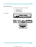
Devices


