Service Instructions VISUCAM
lite
Issue: 22.09.2003
SM-30-4044-A1-en
Replaces issue:
Page
19
of 41
St11
St7
St5
St66
St9
St8
St4
Extended field of view
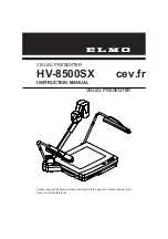
Camera module
Replacing the cameras
•
Open the camera head (see: Opening
and closing the camera head)
•
Remove the cable connections.
•
Screw out 3 fastening screws and
remove the camera module.
•
Insert the new module and align it with
the right-hand edge of the housing.
•
Make electrical connections.
•
Align the module using the right-hand
housing edge in such a way that the
vertical position of the image on the
monitor is correct.
Connectors of the Camera module
Control PCB VISUCAM
lite
, +12V, B/W sensor,
X18
Control PCB VISUCAM
lite
, B/W control,
X16
Control cable VISUCAM
lite
, Signals Y/C,
X131
Control cable VISUCAM
lite
, B/W signal,
X132
Control PCB VISUCAM
lite
, +12V, Color sensor,
X17
Stepper motor for camera shift
The distance between the opto-coupler and B/W camera ranges between >5 and <50 steps.
Outside this range, an error message is displayed (Overflow position error).
Settings: Before starting the service program, deactivate the date and set the translucency to
bright. Defocus the illuminated ring. No external light should reach the camera
sensors. Darken the room.
Positions of the cameras
>5 steps <50
Opto coupler
B/W camera sensor
color camera sensor
⇒
⇒
⇒
⇒
If the positions of both cameras have been
correctly adjusted, both images are centered on
the screen. This is indicated by the black corners.
The extended field of view has an even, circular
shape.
Start the service software (see "
Opening the Test
Tools program"
).
•
Select the
step motors
tab.
•
Select the
shift camera
tab.
There are two alternatives for positioning:
- Click on 0 or set 1 position without camera function.
– Click on 0 or set 1 position with camera function.
•
Adjust the stepper motor by +1/-1 until the opto-
coupler is no longer activated.
⇒
⇒
⇒
⇒
The
mark indicates the transmitted light
function of the opto-coupler.
⇒
⇒
⇒
⇒
If you press the
set home position
button, the
basic position is resumed (B/W camera sensor,
position 0, color camera sensor position 1). If the
opto-coupler functions correctly, HP-okay is
displayed in the
Notification
box.
Note:
The test image function is not used.
Housing edge
Housing edge
Stepper
Opto-coupler
cameras
B/W camera
color camera
Содержание VISUCAM lite
Страница 38: ......