Service Instructions VISUCAM
lite
Issue: 22.09.2003
SM-30-4044-A1-en
Replaces issue:
Page
7
of 41
VISUCAM
lite
- Unit
Notes on servicing:
Always disconnect the power plug before opening the unit.
After servicing, check all functions and, if necessary, the electrical safety of the unit.
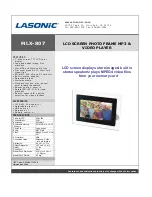
System overview
1 Cap of fixation light
2 Fixation light
3 Headrest with chinrest
4 Monitor
5 USB Flash Drive (Option)
6 Keyboard, Mouse (PS2)
7 Instrument base with joystick and
potentiometer for brightness adjustment
8 Camera head
9 Control base
Design
The base, mechanical stage, instrument head and headrest form one functional unit.
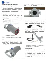
The connector panel on the base provides the following connections:
1 The VISUCAM
lite
is switched on/off using power switch (1).
2 The power cord is connected to power inlet (2).
3 The display is connected to VGA connector (3). (The display has its own power supply
and is not switched on/off using the power switch.)
4 2 USB Ports (4) are available for USB devices (Printer).
5 The camera head is connected to DEVICE connector (5).
6 The Mouse is connected to PS2 Mouse connector (6.
7 The Keyboard is connected to PS2 Keyboard connector (7).
8 Label for connector layout
9 A printer can be connected to LPT1 parallel port (9).
10 COM1 serial port (10) is provided for the connection of serial units.
11 NET network connector (11) for integration of the VISUCAM
lite
in a network.
12 Warning label
VISUCAM
lite
connector panel
9
Содержание VISUCAM lite
Страница 38: ......