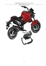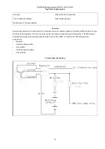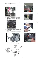
YG48Q-5A Maintenance ManualFront wheel, front suspension device and steering stem
115
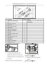
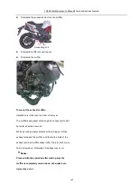
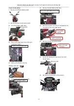
Control subassembly
1
、
Remove the left/right balance weight.
2
、
Remove handle and combination switch
Pull off the brake switch leads
Remove the upper/lower body of the right
combination switch
Remove the throttle control line
Remove the Left combination switch
Remove the right brake cylinder body.
Remove the clutch control line and disassemble the
connection of the clutch switch leads.
Remove the right combination switch.
Loosen the retaining bolt and remove the clutch
handle holder.
Remove the clip and take out the grip tube.
Brake switch
Remove the upper/lower body
Throttle control line
left combination switch
Remove the right brake cylinder body
Retaining bolt
Bolt.
Remove the right
combination
The clutch
handle.
clutch control line
Содержание YG48Q-5A
Страница 38: ...YG48Q 5AMaintenance ManualFuel system 41 4 Fuel system...
Страница 42: ...YG48Q 5A Maintenance ManualRemoval and installation of engine 46 5 Removal and installation of engine...
Страница 92: ...YG48Q 5AMaintenance ManualFrame and exhaust system 105 10 Frame and exhaust system...
Страница 108: ...YG48Q 5A Maintenance ManualRear wheel and rear suspension device 121 12 Rear wheel and rear suspension device...
Страница 123: ...YG48Q 5A Maintenance ManualIllumination signal system 136 Circuit schematic drawing...
Страница 126: ...YG48Q 5A Maintenance ManualIllumination signal system 139...
Страница 133: ...YG48Q 5A Maintenance ManualEngine management system 146 Major parts and components...
Страница 134: ...YG48Q 5A Maintenance ManualEngine management system 147...
Страница 144: ...YG48Q 5A Maintenance ManualElectrical System Diagram 157 19 Electrical System Diagram...

