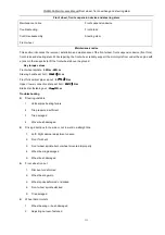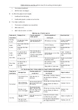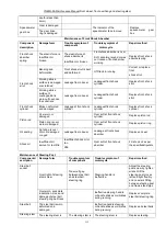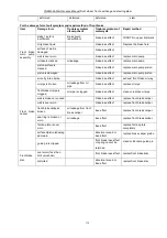
YG48Q-5AMaintenance ManualCrankcase, crankshaft and Shift mechanism
96
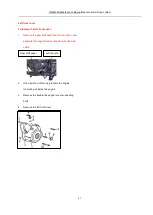
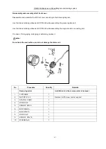
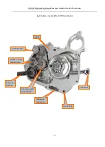
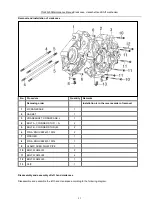
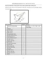
Removal and installation of crankshaft and balance shaft
No.
Procedure
Quantity
Remarks
Removing order
Installation is in the reverse order of removal
1
Left hand crankcase
1
2
Crankshaft
1
3
Knock pin
2
4
GASKET
1
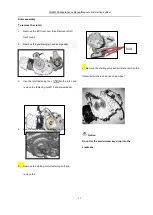
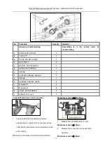
Disassembly and assembly of crankshaft and balance shaft
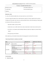
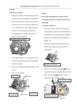
Do not further disassemble the crankshaft, otherwise the spar parts may be damaged.
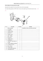
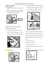
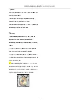
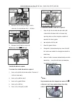
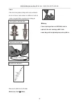
Disassemble and assemble the balance shaft according to the following diagram.
Notice:
Always align the markers while assembling the balance shaft.
4
2
1
3
Содержание YG48Q-5A
Страница 38: ...YG48Q 5AMaintenance ManualFuel system 41 4 Fuel system...
Страница 42: ...YG48Q 5A Maintenance ManualRemoval and installation of engine 46 5 Removal and installation of engine...
Страница 92: ...YG48Q 5AMaintenance ManualFrame and exhaust system 105 10 Frame and exhaust system...
Страница 108: ...YG48Q 5A Maintenance ManualRear wheel and rear suspension device 121 12 Rear wheel and rear suspension device...
Страница 123: ...YG48Q 5A Maintenance ManualIllumination signal system 136 Circuit schematic drawing...
Страница 126: ...YG48Q 5A Maintenance ManualIllumination signal system 139...
Страница 133: ...YG48Q 5A Maintenance ManualEngine management system 146 Major parts and components...
Страница 134: ...YG48Q 5A Maintenance ManualEngine management system 147...
Страница 144: ...YG48Q 5A Maintenance ManualElectrical System Diagram 157 19 Electrical System Diagram...

