YG48Q-5A Maintenance Manual
Inspection and adjustment
27
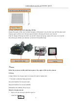
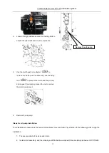
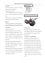
Timing phase
It shall be carried out when the vehicle is new or there is
any question about the timing phase.
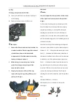
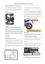
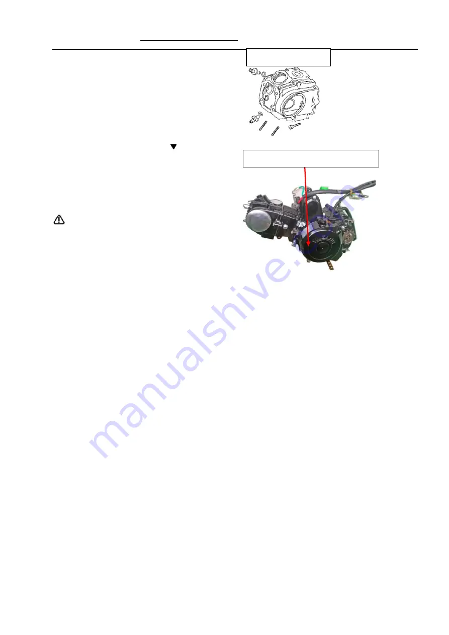
Remove the cylinder head cover
Turn the crankshaft pulley Counterclockwise to align the
scale line “I” with the indication mark “ ” on the front-left
cover.
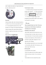
When the piston is at the upper dead point, the scale line
on the camshaft is at the same level with the.
Notice
At this point, the piston must be at the upper dead
point of the compression stroke other than that of the
exhaust stroke.
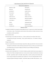
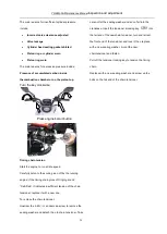
Adjustment of Ignition Time
That the ignition lead angle is not correct will cause a
series of problem that engine is difficult to start
,
power
decrease
,
oil consumption increase
,
engine overheats
,
burning is not complete
,
emission exceed standard
,
use
life reduce and so on
.
So should adjust the ignition lead
angle at first
Need not adjust the ignition timing if engine without
contact ignition
.
If the ignition system is abnormal
,
should
check electronic ignition
,
high-voltage coil
,
charging on
the generator and trigger coil etc.
.
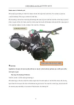
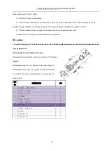
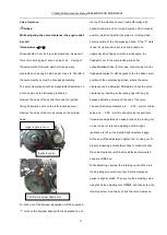
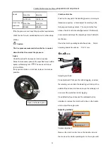
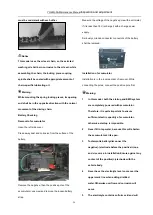
After properly timing, pull off the tensioner locking key and
coat the mixture of engine oil and molybdenum disulfide
on the tensioner to make it tensioned; mount the sprocket
retaining plate and retaining bolt.
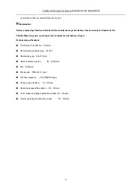
Cylinder pressure
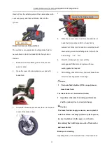
When the engine fails to start or is difficult to start, or
when questioning the cylinder pressure is abnormal after
other possible faults have been excluded, check the
cylinder pressure.
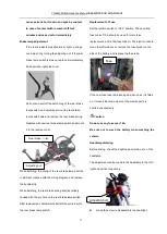
Cylinder pressure:
≥0.8MPa/300r/min.
While testing, remove the spark plug and mount
apressure gauge at the position where the spark plug
ismounted; fully open the throttle bar and electronically
start the engine, and then check all connecting points of
the pressure gauge for gas leak. Zero the pressure gauge
and restart the engine until the pressure gauge reading
stops rising. The maximum reading of the pressure gauge
can usually be reached after 1 or 2 startups. Such
maximum reading shall be the cylinder pressure. Upon
completion of testing, mount the spark plug to its original
position.
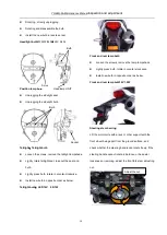
The boss is in the center of the hole
While aligning
Содержание YG48Q-5A
Страница 38: ...YG48Q 5AMaintenance ManualFuel system 41 4 Fuel system...
Страница 42: ...YG48Q 5A Maintenance ManualRemoval and installation of engine 46 5 Removal and installation of engine...
Страница 92: ...YG48Q 5AMaintenance ManualFrame and exhaust system 105 10 Frame and exhaust system...
Страница 108: ...YG48Q 5A Maintenance ManualRear wheel and rear suspension device 121 12 Rear wheel and rear suspension device...
Страница 123: ...YG48Q 5A Maintenance ManualIllumination signal system 136 Circuit schematic drawing...
Страница 126: ...YG48Q 5A Maintenance ManualIllumination signal system 139...
Страница 133: ...YG48Q 5A Maintenance ManualEngine management system 146 Major parts and components...
Страница 134: ...YG48Q 5A Maintenance ManualEngine management system 147...
Страница 144: ...YG48Q 5A Maintenance ManualElectrical System Diagram 157 19 Electrical System Diagram...

