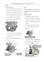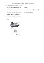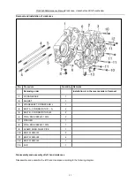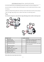
YG48Q-5AMaintenance ManualCrankcase, crankshaft and Shift mechanism
98
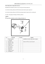
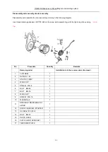
No.
Procedure
Quantity
Remarks
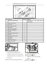
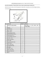
Sequence of disassembling
Assembling is in the reverse order of
disassembling.
1
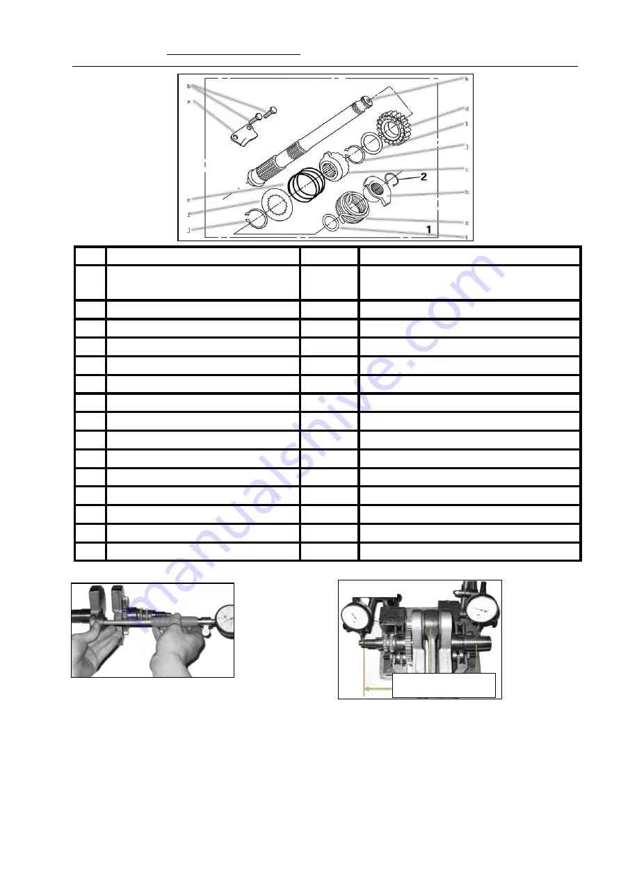
KICK-START SYSTEM
1
2
CIRCLIP 17
,
1
1
a
PLATE, RACHET, GUIDE
1
b
BOLT M6×20
2
c
RACHET, KICK STARTER
1
d
GEAR, KICK STARTER
1
e
SPRING
1
f
SUPPORT, SPRING, RACHET
1
g
SPRING
1
h
SUPPORT, SPRING, START
1
i
WASHER 17
1
j
WASHER 20
2
k
SHAFT, KICK STARTER
1
l
CIRCLIP 20.2×1×27
1
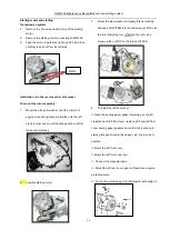
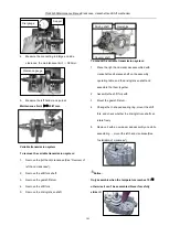
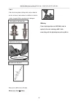
Crankshaft and balance shaft inspection
1.
Check whether the crankshaft journals are
abnormally worn, whether the connecting rod can
rotate flexibly and whether there is significant noise
while rotating.
Measure the connecting rod small end bore diameter.
Maintenance limit:
≤Ф
20.063mm.
2.
Measure the crankshaft radial run out.
Maintenance limit:
≤
0.10mm.
3.
Measure the connecting rod big end radial
clearance.
Maintenance limit:
≤
0.06mm.
Inside micrometer
Содержание YG48Q-5A
Страница 38: ...YG48Q 5AMaintenance ManualFuel system 41 4 Fuel system...
Страница 42: ...YG48Q 5A Maintenance ManualRemoval and installation of engine 46 5 Removal and installation of engine...
Страница 92: ...YG48Q 5AMaintenance ManualFrame and exhaust system 105 10 Frame and exhaust system...
Страница 108: ...YG48Q 5A Maintenance ManualRear wheel and rear suspension device 121 12 Rear wheel and rear suspension device...
Страница 123: ...YG48Q 5A Maintenance ManualIllumination signal system 136 Circuit schematic drawing...
Страница 126: ...YG48Q 5A Maintenance ManualIllumination signal system 139...
Страница 133: ...YG48Q 5A Maintenance ManualEngine management system 146 Major parts and components...
Страница 134: ...YG48Q 5A Maintenance ManualEngine management system 147...
Страница 144: ...YG48Q 5A Maintenance ManualElectrical System Diagram 157 19 Electrical System Diagram...

