72
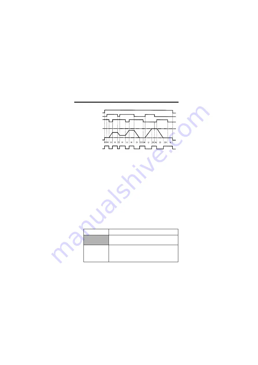
Time Chart for UP/DOWN Command Input
Note: 1. When UP/DOWN commands are selected, the upper limit speed is set
regardless of frequency reference.
Upper limit speed =Maximum Output Frequency (n09)
×
Frequency Reference Upper Limit (n30)/100%
2. Lower limit value is either the Minimum Output Frequency (n14) or
Maximum Output Frequency (n09)
×
Frequency Reference Lower
Limit (n31)/100% (whichever is larger.).
3. When the FWD (REV) RUN command is input, operation starts at the
lower limit speed without using the UP/DOWN commands.
4. If the JOG command is input while running for an UP/DOWN com-
mand, the JOG command has priority.
5. Multi-step speed references 1 to 3 are not effective when an UP/
DOWN command is selected. Multi-step speed references are effec-
tive while running in hold status.
6. When 1 is set for the HOLD Output Frequency Memory Selection
(n62), the output frequency can be recorded during HOLD.
Setting
Description
0
Output frequency is not recorded during
HOLD.
1
When HOLD status is continued for 5 seconds
or longer, the output frequency during HOLD
is recorded and the Inverter restarts at the re-
corded frequency.
FWD RUN
UP Command S4
DOWN Command S5
Upper Limit Speed
Lower Limit Speed
Output Frequency
FREQUENCY Agree
Signal
U = UP (accelerating) status
D = DOWN (decelerating) status
H = HOLD (constant speed) status
U1 = UP status, clamping at upper limit speed
D1 = DOWN status, clamping at lower limit speed


