62
VS-616PS5 Programming Manual
Section H: Control Circuit Terminal Parameters
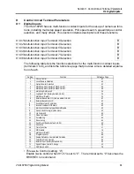
H1 Digital Intputs
• Local/Remote Selection (setting: “1”)
Selects the operation mode, only when the inverter is stopped.
Local:
Operation according to frequency reference and run command as
entered from digital operator.
Remote: Operation according to frequency reference and run command set by
B1-01
&
B1-02
, respectively.
Note: When local/remote selection is set by a multi-function contact input ter-
minal, local/remote selection from the digital operator key is disabled.
• Option/Inverter Selection (setting: “2”)
Selects whether operation is performed using a reference command from an option
card or from the inverter. Changeover is effective only when the inverter is stopped.
Open:
Runs by frequency reference and run command from inverter control
circuit terminal or digital operator (B1-01 & B1-02 dependant).
Closed:
Runs by frequency reference and run command from an option card.
• External Baseblock N.O. (setting: “8”)
Baseblock operation is performed when the contact input is closed. External base-
block operation differs, as described below, depending on the run command input
status.
Inputting an external baseblock signal while the inverter is running, causes a “
BB
”
indication on the digital operator display, and the inverter output is shut OFF.
After removing the external baseblock command, operation restarts at the previ-
ously referenced speed.
Inputting a stop signal along with an external baseblock signal while the inverter is
decelerating, causes”
BB
” to blink on the digital operator, the inverter output to shut
OFF, and the frequency reference to reset to 0.
• External Baseblock N.C. (setting: “9”)
Baseblock operation is performed similar to setting “8,” except that operation is per-
formed when the contact input is open.
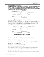
• Accel/Decel Hold Command (setting: “A”)
The accel/decel hold command is used to temporarily hold the output speed at its
current level at the time the “Hold” command is applied. Upon entry of a stop com-
mand, the accel/decel hold condition releases and operation stops.
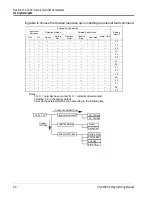
Figure 31 Terminal Function at 3-Wire Sequence Selection (H1-01 = “0”)
1
2
11
Run Command
(Run when “Closed”)
Stop Command
(Stop when “Open”)
FWD/REV Selection
(FWD when “Open”
REV when “Closed”)
5
Stop
Run


