5.3 Addressing
5.3.1 Overview
To provide specific addressing of the installed peripheral modules, certain addresses
must be allocated in the CPU. At the start-up of the CPU, this assigns automatically
peripheral addresses for digital in-/output modules starting with 0 and ascending
depending on the slot location.
If no hardware project engineering is available, the CPU stores at the addressing analog
modules to even addresses starting with 256.
5.3.2 Addressing Backplane bus I/O devices
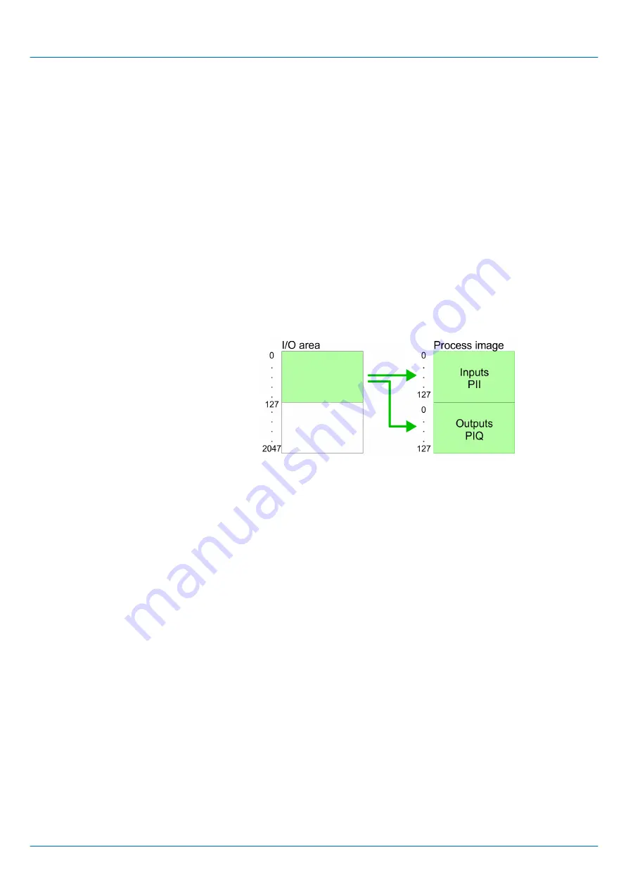
The CPU 315-4PN23 provides an I/O area (address 0 ... 2047) and a process image of
the in- and outputs (each address 0 ... 127).
The process image this divided into two parts:
n
process image to the inputs (PII)
n
process image to the outputs (PIQ)
The process image is updated automatically when a cycle has been completed.
Maximally 8 modules per row may be configured by the CPU 315-4PN23.
For the project engineering of more than 8 modules you may use line interface connec-
tions. For this you set in the hardware configurator the module IM 360 from the hardware
catalog to slot 3 of your 1. profile rail. Now you may extend your system with up to 3 pro-
file rails by starting each with an IM 361 from Siemens at slot 3. Considering the max total
current with the CPU 315-4PN23 from VIPA up to 32 modules may be arranged in a row.
Here the installation of the line connections IM 360/361 from Siemens is not required.
You may access the modules with read res. write accesses to the peripheral bytes or the
process image.
To define addresses a hardware configuration may be used. For this, click on the proper-
ties of the according module and set the wanted address.
If you do not like to use a hardware configuration, an automatic addressing comes into
force. At the automatic address allocation DIOs occupy depending on the slot location
always 4byte and AIOs, FMs, CPs always 16byte at the bus. Depending on the slot loca-
tion the start address from where on the according module is stored in the address range
is calculated with the following formulas:
n
DIOs: Start address = 4×(slot -1)
n
AIOs, FMs, CPs: Start address = 16×(slot -1)+256
Max. number of pluggable
modules
Define addresses by hard-
ware configuration
Automatic addressing
System 300S
+
Deployment CPU 315-4PN23
Addressing > Addressing Backplane bus I/O devices
HB140 | CPU | 315-4PN23 | en | 18-02
38
Содержание SPEED7 300S+ CPU 315PN
Страница 1: ...CPU 315 4PN23 Manual HB140 CPU 315 4PN23 en 18 02 System 300S SPEED7 CPU 315PN...
Страница 89: ...System 300S Deployment PtP communication Modbus Example communication HB140 CPU 315 4PN23 en 18 02 89...
Страница 155: ...Appendix System 300S Appendix HB140 CPU 315 4PN23 en 18 02 155...


