Input channels
Reference Manual
42
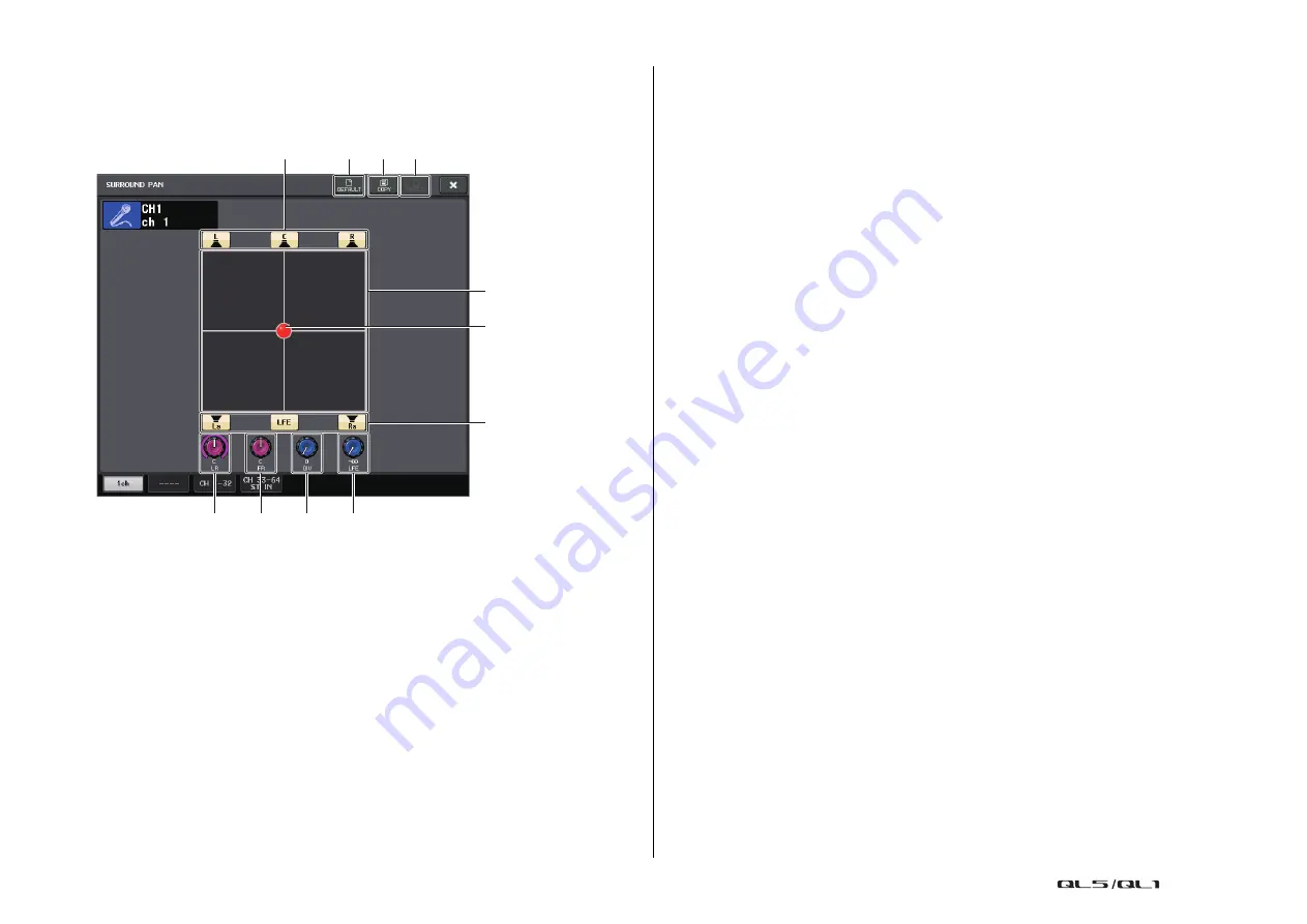
SURROUND PAN 1CH screen
If you set a bus to Surround mode in BUS SETUP, the SURROUND PAN 1CH screen appears
as shown below. This screen is displayed when you press the pan display area in the
SELECTED CHANNEL VIEW screen or the OVERVIEW screen.
1
Surround graph
This graph shows the surround positions.
2
Surround position
You can set the surround position by touching and dragging the ball in the graph.
3
Assign buttons for each bus
All of these buttons are turned on by default. If there is a bus from which you do not
want to output an audio signal, turn that button off.
4
L/R knob
This parameter is used to set the left/right surround position.
You can use the [TOUCH AND TURN] knob to adjust this.
5
F/R knob
This parameter is used to set the front/rear surround position.
You can use the [TOUCH AND TURN] knob to adjust this.
6
DIV knob
This determines how the Center signal is fed to the Left, Right, and Center channels.
When set to 0, the Center signal is fed only to the Left and Right channels. When set to
50, the Center signal is fed equally to the Left, Right, and Center channels. When set to
100, it’s fed to only the Center channel (i.e., Real Center).
You can use the [TOUCH AND TURN] knob to adjust this.
7
LFE knob
This sets the level of the LFE (Low Frequency Effects) Channel.
You can use the [TOUCH AND TURN] knob to adjust this.
8
DEFAULT button
Press this button to reset all parameters to the initial values.
9
COPY button
All parameter settings will be copied in buffer memory.
0
PASTE button
Press this button to paste the copied settings from buffer memory to the current
settings. If no valid data has been copied in the buffer memory, nothing will happen.
>
9
1
3
8
6
7
5
4
3
2


