


Copyright ©2018, 2020 ASSA ABLOY Access and Egress Hardware Group, Inc. All rights reserved. Reproduction in whole or in
part without the express written permission of ASSA ABLOY Access and Egress Hardware Group, Inc. is prohibited
For technical support contact Yale
®
at 800.438.1951 x5033 or [email protected]
9
Delayed Egress
7100, 7200 Series Exit Device
Installation Instructions
80-9470-0162-000 10/20
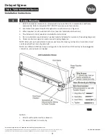
6
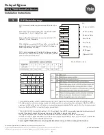
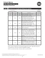
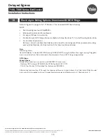
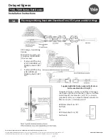
Wiring Layout: Input/Output Wiring Descriptions
Pin Number
Input/Output
Wire Color
Description
Pin Number
10
Input
Black
24VDC Power Supply (-Circuit Ground)
1
12
Input
Red
24VDC Power Supply (+Positive)
2
11
Output
White
Secure Relay Output - Normally Open (NO)
contact. Power off - contact is open
Powered/armed - Relay energizes contact
closes. After 15 or 30 seconds delay when
device releases, the relay de-energizes, contact
opens (same as Power off state).
3
13
Output
Green
Secure Relay Output - Normally Closed (NC)
contact. Power off - contact is closed.
Powered/armed - Relay energizes, contact
opens. After 15 or 30 seconds delay when
device releases, relay de-energizes, contact is
closed (same as Power off state).
4
NC
EGND
Orange
Earth Ground connection to PCB mounting
plate via ring terminal
5
3
Output
Blue
Alarm Relay Output - J5 jumper Selectable
NO/NC contact that changes state when alarm
cycle has been activated. Default shipped
position - jumper is on NO contact setting.
Power off - contact is NO or NC as per jumper
selection.Powered/armed - Relay energizes
contact reverses state. When alarm cycle is
activated - Relay de-energizes (same as Power
off state).
6
8
Input
Brown
Remote Reset Input - Momentary input from
key switch, pushbutton, etc. Will release
device for 5, 10, 20, or 40 seconds for egress or
ingress and also reset device when in bypass or
alarmed state.
7
6
Input
Yellow
Remote Bypass Input - Momentary input from
key switch, pushbutton, etc. Will maintain
device in an unlocked state for normal device
operation. Device must be rearmed by resetting
from key switch on device or remote reset.
8
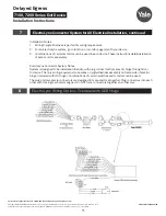
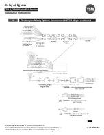
J2 Connector
(See Figure 5 on next page)
8-Pin
ElectroLynx
Connector
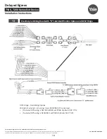
NOTE: ElectroLynx QC8 Hinge is only required if all eight wires are used. When DPS and any other
wiring options are on the 4-pin connector, the hinge is NOT required.
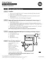
NOTE: Secure and Alarm Relay contacts are rated max load 1A @24VDC.