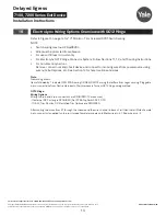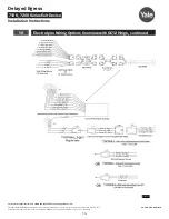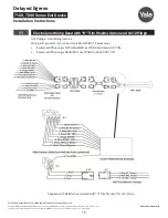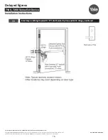
Copyright ©2018, 2020 ASSA ABLOY Access and Egress Hardware Group, Inc. All rights reserved. Reproduction in whole or in
part without the express written permission of ASSA ABLOY Access and Egress Hardware Group, Inc. is prohibited.
For technical support contact Yale
®
at 800.438.1951 x5033 or [email protected]
4
Delayed Egress
Installation Instructions
7100, 7200 Series Exit Device
80-9470-0162-000 10/20
1
Panic and Fire Rated Devices
1. Check device for shipping damage prior to installation and make sure all parts are on hand.
2. Identify options provided with device.
3. Identify model, type and hand of trim if applicable (see exit device and trim instructions for
reversing hands).
4. Contact hardware supplier if device is damaged or missing parts.
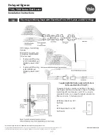
a
Checklist
b
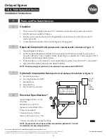
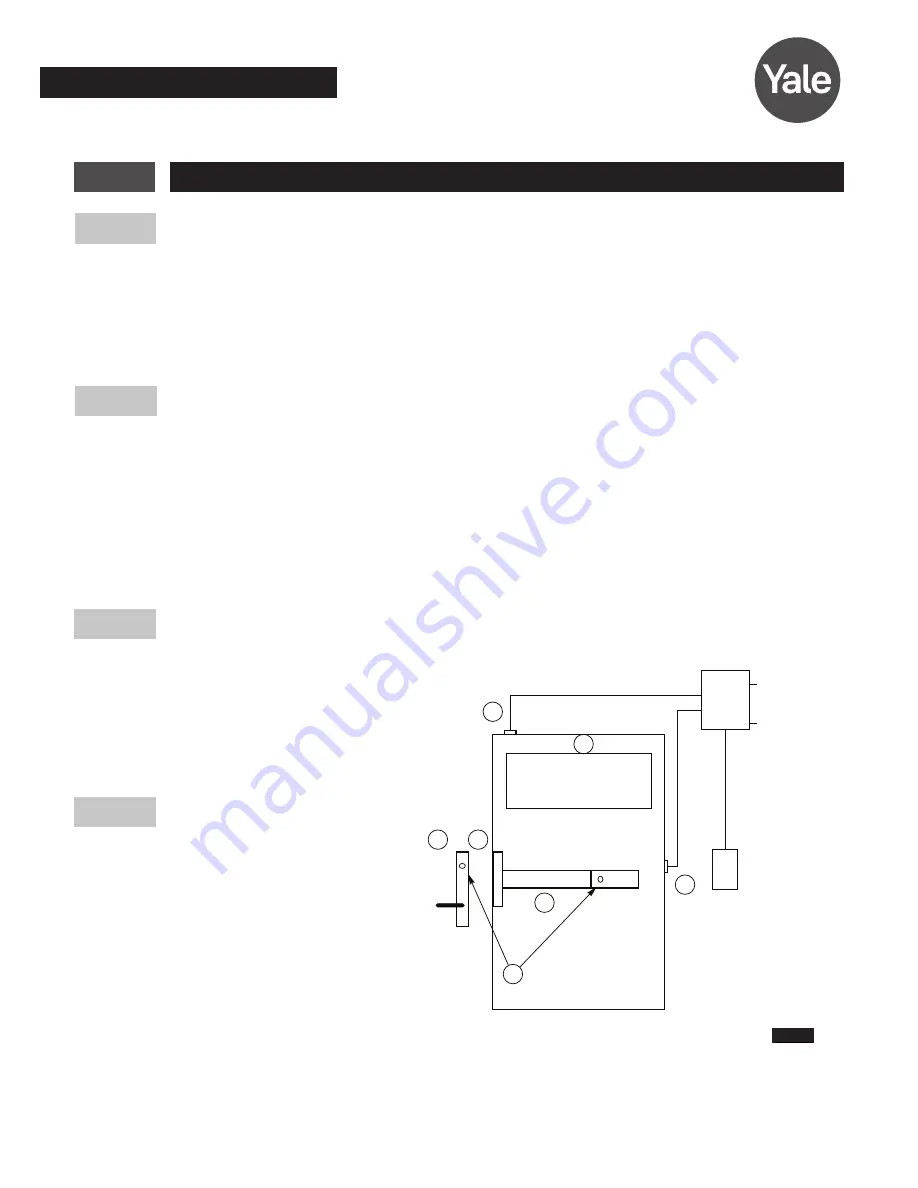
Required Components
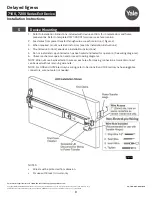
(Numbered list correlates with numbers in Fig
ure 1)
c
Optional Components
(Numbered list correlates with numbers in Fig
ure 1)
1. Delayed Egress Exit Device
2. 24VDC UL Listed Regulated and Filtered Power Supply with Fire Alarm Interface (recommend
Securitron BPS 24-1 or 24-2 (UL294 Listed), depending on requirements). Power supply is NOT to
be used in UL603 Burglar Alarm System.
3. Power transfer UL or ULC listed (2-10 wire depending on system)-Securitron (EPT) or equivalent.
4. Sign (MUST BE INSTALLED ON DOOR ABOVE DEVICE).
NOTE: The delayed egress system is to be installed in accordance with NFPA 101.
5. Remote
Annunciator
6. Door Position Switch (DPS)
7. Standard
Trim
8. Electrified
Trim
9. Device and Trim Cylinder
d
Electrical Specifications*
Input Voltage 24VDC (+/-10%)
Wire Size:
18 AWG Min (up to 100')
Signal or Control 22AWG Min
Power Consumption:
Standard Device - 500mA
Device with Electric Trim - 1.5A
*Follow Local Electrical Codes for Wiring.
NOTE: Components shown do not reflect all possible applications. Consult
manufacturer for special applications.
Figure 1
6.
4.
PUSH UNTIL ALARM
SOUNDS. DOOR CAN BE
OPENED IN 15 SECONDS.
3.
5.
1.
8.
7.
9.
115 VAC
1 or 2A
60 Hz
Fire
Alarm
Circuit
Required
Or
2.


