Copyright ©2018, 2020 ASSA ABLOY Access and Egress Hardware Group, Inc. All rights reserved. Reproduction in whole or in
part without the express written permission of ASSA ABLOY Access and Egress Hardware Group, Inc. is prohibited.
For technical support contact Yale
®
at 800.438.1951 x5033 or [email protected]
8
Delayed Egress
Installation Instructions
7100, 7200 Series Exit Device
80-9470-0162-000 10/20
5
Device Mounting
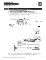
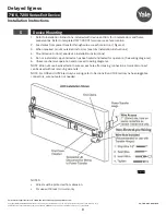
1. Refer to installation instructions included with device and trim for complete door and frame
preparations. Refer to template #7477-00001 for wire access hole location.
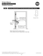
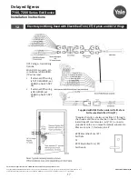
2. Feed wires from power transfer through wire access hole in door. (Figure 4)
3. When required, mount outside trim to door (see trim installation instructions).
4. Mount device to door (see device installation instructions).
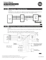
5. Do not install end cap until device has been wired and tested for operation (See wiring diagrams).
6. Check mechanical operation and proceed to wiring diagrams.
NOTE: Wire nuts can be inserted into wire access hole after making connections. Quick disconnect
can be used without removing wire nuts.
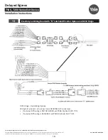
NOTE: For QC8 and QC12 ElectroLynx wiring, refer to Sections 8 and 10. ElectroLynx has pluggable
connectors, wire nuts are not needed.
Figure 4
NOTES:
•
Wires must be protected from abrasion.
•
For use with Class II circuits only.


