background image

Xtreme Power Conversion Corporation

G90 User’s Manual

Page 15

Uninterruptible Power Supply

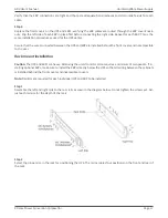
Attach the UPS front cover by reversing the process in Step 1 – installing the LCD side first and then gently snapping 

the other side into the ports on the UPS.

Step 4

If you are installing power management software, connect your computer to one of the communication ports or 

optional connectivity card, using appropriate cable.

Step 5

If your rack has conductors for grounding or bonding of ungrounded metal parts, connect the ground cable (not 

supplied) to the ground bonding screw on the rear of the UPS as shown in the example below.

Step 6

If  an  emergency  power  off  (disconnect)  switch  is  required  by  local  codes,  see  “Remote  Emergency  Power  off 

(REPO)” section to install the REPO switch before powering on the UPS.

Continue to “UPS Internal Startup”.

Connecting Extended Battery Packs (EBPs)

Step 1

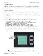
Remove the front cover of the UPS and each EBP by holding in the cover side with the LCD display, then un-snap 

the other side of the front panel from the UPS. The front panel should now easily be removed from the LCD side.

Note: 

a ribbon cable connects the LCD to the cover of the UPS. Do not pull on the cable or disconnect it.

Содержание G90

Страница 1: ...G90 Online UPS 1000VA 2000VA 3000VA Models User Installation Manual www xpcc com 2015 Xtreme Power Conversion Corporation All rights reserved Rev 2 5 15 ...

Страница 2: ...n Guide 12 SafetyInformation 12 Storage and Transportation 12 Environment 13 UPSInstallation 13 Connecting the UPS Internal Batteries 13 Connecting Extended Battery Packs EBPs 15 Rack mountInstallation 17 Tower Installation 19 UPSInputConnection 21 UPSOutputConnection 21 Starting the UPS 21 Operations 23 Front Panel Control Functions 23 IndicatorDescriptions 23 Button Descriptions 24 Working Statu...

Страница 3: ...36 Troubleshooting 39 Fault Codes 40 UPS Maintenance 40 UPS and Battery Care 40 Storing the UPS and Batteries 41 Maintenance 41 Replacing Batteries QUALIFIED SERVICE PERSONNEL ONLY 41 Replacing Battery Trays in UPS and EBPs 42 Specifications 45 Shipping List 46 Obtaining Service 47 Xtreme Power Conversion Limited Warranty 48 Appendix A G90 EBP1 G90 EBP2 User Guide 49 Introduction 49 Installation 4...

Страница 4: ...s important information that should be followed during installation and maintenance of the UPS and batteries allowing you to correctly set up your system for the maximum safety and performance Included is information on customer support and service if it is required If you experience a problem with the UPS please refer to the Troubleshooting section in this manual to correct the problem If the pro...

Страница 5: ...dispose of batteries in a fire the battery may explode CAUTION Do not open or mutilate the battery released electrolyte is harmful to the skin and eyes CAUTION A battery can present a risk of electric shock and high short circuit current The following precaution should be observed when working on batteries Remove watches rings or other metal objects Use tools with insulated handles To reduce the r...

Страница 6: ... personnel Before conducting any maintenance repair or shipment first ensure that everything is turned off com pletely and disconnected For additional safety instructions please use the Safety Manual as a reference Special Symbols The following symbols used on the UPS warn you of precautions RISK OF ELECTRIC SHOCK Please observe the warning that a risk of electric shock is present CAUTION REFER TO...

Страница 7: ...power company ac cidents and radio transmission motors air conditioners and vending machines Protection of sensitive electrical equipment is vital to protect against power outages low or high voltage conditions slow voltage fluctuations frequency variations differential and common mode noise transients etc To prevent power line problems from reaching critical systems causing damage to software har...

Страница 8: ...n Planning a UPS system the following should be taken into consideration The total demand of the protected system shall dictate the output power rating VA Allow a margin for future expansion or calculation inaccuracies from measured power requirements Backup time required will indicate the battery size needed If the load is less than the UPS nominal power rating then actual backup time is longer T...

Страница 9: ...Xtreme Power Conversion Corporation G90 User s Manual Page 9 Uninterruptible Power Supply UPS FRONT VIEW EBP FRONT VIEW G90 1000 REAR VIEW DIAGRAM G90 2000 REAR VIEW DIAGRAM G90 3000 REAR VIEW DIAGRAM ...

Страница 10: ...ONT PANEL Communication Connections To allow for unattended UPS shutdown start up and status monitoring connect one end of the communication cable to the USB RS232 port and the other to the communications port on your PC or server With the monitoring software installed the UPS can be scheduled for shutdown start up and monitoring of the UPS status through the PC or server ...

Страница 11: ...Since the EPO shuts down the equipment immediately orderly shutdown proce dures are not followed by any power management software The UPS will have to be manually restarted in order to regain power to the outlets on the UPS Keep Pin 1 and Pin 2 closed for UPS normal operation To activate EPO function cut the wire between Pin 1 and Pin 2 Warning The EPO circuit is an IEC 60950 safety extra low volt...

Страница 12: ...ore in temperatures outside the range of 15 C to 25 C Ensure that the equipment is fully protected from wet or damp areas and from moist air In order to maintain the batteries the UPS should be recharged every 6 months for at least 8 hours If flammable substances such as gases or fumes are present or if the room is airtight a hazardous situation may exist in which no electrical equipment should be...

Страница 13: ...here is 100mm behind and 50mm on the sides of the UPS for proper ventilation Ensure that the front of the UPS remains clear for user operation UPS Installation Installation and wiring must be performed in accordance with the local electrical laws and regulations and per formed by appropriate personnel For safety considerations the UPS is shipped from the factory without connecting the battery wire...

Страница 14: ...y and firmly Connect the internal battery connector connect red to red pressing the connector tightly together to ensure proper connectivity If installing an Extended Battery Pack EBP see the section titled Connecting EPBs before continuing with the UPS installation Step 3 Replace the UPS front cover verifying that the ribbon cable is protected and if EBPs are installed that the EBP cable is route...

Страница 15: ...ts connect the ground cable not supplied to the ground bonding screw on the rear of the UPS as shown in the example below Step 6 If an emergency power off disconnect switch is required by local codes see Remote Emergency Power off REPO section to install the REPO switch before powering on the UPS Continue to UPS Internal Startup Connecting Extended Battery Packs EBPs Step 1 Remove the front cover ...

Страница 16: ... EBP Cable Knockout on the top and bottom of the EBP front cover Step 3 Caution A small amount of arcing may occur when connecting the internal batteries This is normal and will not harm personnel Connect the cables quickly and firmly Connect the EBP cables into the battery connector s connecting black to black press the connectors tightly together to ensure proper connection To connect the second...

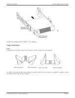
Страница 17: ...are installed behind the front covers and not accessible to the user Rack mount Installation Caution The UPS and EBPs are heavy Removing the units from its carton requires a minimum of two people If in stalling optional EBPs make sure to install the EBPs directly below the UPS so that all wiring between the cabinets is installed behind the front covers and inaccessible to users Note Rail Kits are ...

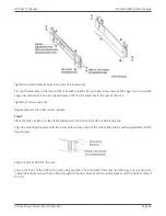
Страница 18: ...Tighten all screws and nuts Repeat steps for the other rail assemblies Step 3 Place the UPS or EBP on a flat stable surface with the front of the UPS or EBP facing you Align the mounting brackets with the screw holes on each side of the UPS or EBP and fix with supplied M4 x 8 flat head screws Slide the UPS or EBP into the rack Secure the front of the UPS to the rack using one M5 x 12 pan head scre...

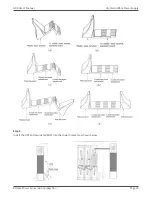
Страница 19: ...additional UPS or EBP for the installation Tower Installation Step 1 Two plastic base brackets intercross and flatten to make a single unit tower bracket If an EBP is to be placed in the tower configuration with the UPS extension boards are added in the middle to make the tower bracket larger as shown below ...

Страница 20: ...Xtreme Power Conversion Corporation G90 User s Manual Page 20 Uninterruptible Power Supply Step 2 Install the UPS and associated EBPs into the tower brackets as shown below ...

Страница 21: ...e UPS 2 Plug the equipment to be protected into the UPS but do not turn on the protected equipment 3 Make any necessary provisions for cord retention and strain relief 4 Plug the detachable UPS power cord into the input connector on the UPS rear cover 5 Plug the UPS power cord into a power outlet The UPS front cover display illuminates 6 The UPS will do a self test when power on After the self tes...

Страница 22: ...put line frequency input frequency auto sensing is enabled by default Note At initial startup please set the output voltage needed before startup of the UPS After the subsequent startup the UPS will output the setting voltage 12 If you installed an optional EPO test the EPO function Activate the external EPO switch Verify the status change on the UPS front panel display Deactivate the external EPO...

Страница 23: ...ree button segmental LCD with backlighting It provides useful information about the UPS load status measurements and settings Indicator Descriptions Indicator Description ON The UPS has an active alarm ON The UPS is in Bypass Mode The UPS is operating normally on bypass during High Efficiency operation ON The UPS is in Battery Mode ON The UPS is operating normally Note When power on or during star...

Страница 24: ...iew of the items every 2 seconds when press and hold the button for some time again display will turn to output status Function Setting Mode Press and hold the button for more than 1 second less than 2 seconds affirm the Set Option Press and hold the button for more than 2 seconds to exit from this function setting interface Setting entry Non function Setting Mode Press and hold the key for more t...

Страница 25: ...y Mode 2 per second Remove uncritical loads Overload in Battery Mode protection Long beeps Remove uncritical loads 6 Overload warning in Bypass Mode Once every 2 seconds Remove uncritical loads 7 Fan fault fan icon flashing Once every 2 seconds Check if the fan is blocked by an object 8 Fault Mode Long beeps If display fault code and icon lights contract dealer dis tributor or manufac turer for ad...

Страница 26: ...ad reaches 40 60 3 panes When the UPS is overloaded the icon will flash when the battery is weak or discon nected the icon will also flash Fan status graphics section Display if the fan works normally When the fan works normally it will show the dynamic fan blades rotating when the fan works ab normally the icon will keep flash ing with the warning Charger status graphics section Displays the stat...

Страница 27: ...o output status Item Description Graphic Output Display the output voltage and output frequency of the UPS As shown in the graphic the output voltage is 230V and the output frequency is 50Hz Load Display the numerical value of the active power WATT and apparent power VA of the load As shown in the graphic the WATT of the load is 100W the VA is 100VA when the load is disconnected it is normal for a...

Страница 28: ...As shown in the graphic the battery voltage is 38V the capacity of the battery is 100 the capacity of the battery is an estimate based upon the battery voltage Battery remaining time Display the battery remaining time when under battery mode The number is from 0 to 999 minutes As shown in the graphic there are 686 minutes of battery time remaining ...

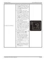
Страница 29: ...lash Press and hold the scroll but ton for more than second less than 2 seconds to determine whether the ECO function is en abled or disabled 3 Confirm the ECO selecting inter face After selecting ON or OFF press and hold the function setting button for more than sec ond less than 2 seconds Now the ECO setting function is completed and the ON or OFF below the ECO will light without flashing 4 If O...

Страница 30: ...BPS function is en abled or disabled 3 Confirm the BPS selecting inter face After selecting ON or OFF press and hold the function setting button for more than sec ond less than 2 seconds Now the BPS setting function is completed and the ON of OFF below the bPS will light without flashing 4 If OFF is chosen go to step 7 otherwise go to step 5 5 Set the BPS tolerance range Briefly press the scroll b...

Страница 31: ... the function setting button for more than 2 seconds to exit setting menu 4 Battery string number and type setting 1 Enter the setting interface Press and hold the function setting but ton for more than 2 seconds stepping through using the scroll button until reaching the bAt flashing 2 Enter the setting interface Press and hold the function setting but ton for more than 2 seconds stepping through...

Страница 32: ...nd less than 2 seconds Now the load shielding battery voltage setting is confirmed 4 Press the function setting button for more than 2 seconds to exit setting menu 6 EPO Input Polarity setting 1 Enter the setting interface Press and hold the function setting but ton for more than 2 seconds stepping through using the scroll button until reaching the EPO flashing 2 Enter the setting interface Press ...

Страница 33: ...tes the indicator of flashes If the Battery voltage reaches the low limit the UPS will turn off to protect the Battery The UPS will auto restart when the input utility power returns Note The backup time of Battery Mode is subject to the load connected and the EBPs installed Battery remaining time displayed on the LCD may not be completely accurate Bypass Mode Bypass yellow LED is on the buzzer bee...

Страница 34: ...in this mode Startup Operation Startup UPS in Line Mode 1 Once the utility power is connected to the UPS the UPS will charge the battery The LCD shows that the output voltage is 0 which means the UPS has no output If it is desired to have Bypass output set the BPS to ON by LCD setting menu 2 Press and hold the ON Button for more than second to start the UPS The UPS will start the inverter 3 Once s...

Страница 35: ...e second it will restart the audible alarm Configuring Battery Settings Set the UPS for the number of EBPs installed To ensure maximum battery runtime configure the UPS for the correct number of EBPs per the table below Use the up and down scroll buttons to select the number of battery strings according to your UPS configuration UPS EBP Units Number of Battery Strings UPS only internal batteries 1...

Страница 36: ...ry cable s and connect the cables to the appropri ate location 2 Route and tie the cable s properly 3 Continue to Operation section in this manual to startup UPS Communication Options The UPS has serial communication capabilities through the USB and RS232 communication ports or through a con nectivity card in the available communication bay The UPS supports two serial communication devices accordi...

Страница 37: ...umidity temperature smoke alarm and security information Relay Interface Card has isolated dry contact relay outputs for UPS status including utility failure low bat tery UPS alarm OK or On bypass Note Before installing the connectivity card please remove the cover from the Intelligent Card Slot Emergency Power Off EPO EPO is used to shut down the UPS from a distance This feature can be used for s...

Страница 38: ...urn on the UPS manually Maximum resistance in the shortened loop is 10 ohm Note Always test the EPO function before applying your critical load to avoid accidental load loss Load Segments Load segments are sets of receptacles that can be controlled by power management software or through the display providing for an orderly shutdown and startup of equipment For example during a power outage critic...

Страница 39: ...ind on the UPS when problems are experienced The user can judge if the fault is caused by external factors and determine how to deal with the problem by using this information If the Fault LED is on it indicates that the UPS had detected some faults The buzzer beeps to indicate that the UPS needs to be checked if beeping continues it indicates that there is something wrong with the UPS requiring s...

Страница 40: ...r Fault 20 39 Over Heat 40 44 Output Short Circuit 45 49 Overload 50 54 Output Relay Fault 55 59 Input NTC Fault 60 64 Auxiliary Power Fault 65 69 Input Fuse Fault 70 74 Others 99 UPS Maintenance This section explains how to Care for the UPS and batteries Replace Extended Battery Packs EBPs Test new batteries Recycle used batteries or UPS UPS and Battery Care For the best preventative maintenance ...

Страница 41: ...uthorized persons must be kept well away from the batteries Verify that no voltage between the battery terminals and the ground is present before maintenance or repair In this product the battery circuit is not isolated from the input voltage Hazardous voltages may occur between the battery terminals and the ground Batteries may cause electric shock and have a high short circuit current Please rem...

Страница 42: ...ls 6 Determine if the battery is inadvertently grounded If inadvertently grounded remove the source of the ground Contact with a grounded battery can result in electrical shock The likelihood of such shock will be reduced if such grounds are removed during installation and maintenance applicable to a UPS and a remote battery supply not having a grounded circuit Note DO NOT DISCONNECT the batteries...

Страница 43: ...the UPS or EBP Testing New Batteries To test new batteries 1 Plug the UPS into a power outlet for 48 hours to completely charge the batteries 2 Start up the UPS by pressing the startup combination buttons 3 Press the Battery Test combination buttons to activate the battery test The UPS starts a battery test if the batteries are fully charged ...

Страница 44: ...tery or UPS Warning Do not dispose of the battery or batteries in a fire Batteries may explode Proper disposal of batteries is required Refer to local codes for disposal requirements Do not open or mutilate the battery or batteries Released electrolyte is harmful to skin and eyes It may be toxic Caution Do not discard the UPS or the UPS batteries in the trash This product contains sealed lead acid...

Страница 45: ...5 7 lbs 28 1 kg 61 9 lbs 29 2 kg 64 4 lbs EBP dimensions 440 x 430 x 86 5 mm 440 x 690 x 86 5 mm W x D x H 17 3 x 16 9 x 3 4 in 17 3 x 27 2 x 3 4 in EBP weight 24 0 kg 52 9 lbs 46 0 kg 101 4 lbs ENVIRONMENT Temperature 0 40 C 32 104 F Humidity 0 95 non condensing Altitude 3500 m 11 500 ft above sea level APPROVALS CE EN 61000 IEC EN 62040 WARRANTY 2 years electronics 2 years battery COMMUNICATIONS...

Страница 46: ...eme Power Conversion Corporation G90 User s Manual Page 46 Uninterruptible Power Supply Shipping List 1 User Manual 2 Rack mount brackets 3 Tower stands 4 Power cord 5 Software CD 6 USB cable 7 RS232 cable ...

Страница 47: ...ask you for the above information and if possible help solve your problem over the phone In the event that the unit requires factory service the technician will issue you a Return Mate rial Authorization number RMA If you are returning the UPS to Xtreme Power for service please follow these procedures 1 Pack the UPS in its original packaging If the original packaging is no longer available ask the...

Страница 48: ...subjected to an adverse operating environment or is operated outside the limits of its electrical specifi cations or c the equipment has been used or stored in a manner contrary to the equipment s operating manual intended use or other written instructions Any technical advice furnished by XPC Corporation or a XPC Corpora tion authorized representative before or after delivery with regard to the u...

Страница 49: ...e reference CAUTION Batteries can prevent a risk of electrical shock or burn from high short circuit current Observe proper precautions Servicing should be performed by qualified service personnel knowledgeable of batteries and re quired precautions Keep unauthorized personnel away from batteries CAUTION Proper disposal of batteries is required Refer to your local codes for disposal requirements C...

Страница 50: ...l Insert the EBP cable into the UPS battery connector quickly and firmly Up to four EBPS may be connected to the UPS Connect red to red black to black and yellow to yellow Press the two parts tightly together to ensure a proper connection To connect a second EBP unclip the EBP connector on the first EBP and pull gently to extend the wiring to the EBP connector on the second EBP Repeat for any addi...

Страница 51: ...nfiguration All UPS and EBP Cabinets Number of Battery Strings UPS only internal batteries 1 default UPS 1EBP 3 UPS 2EBPs 5 UPS 3EBPs 7 UPS 4EBPs 9 Note The UPS contains one battery string each EBP contains two battery strings Maintenance Replacing Batteries NOTE DO NOT DISCONNECT the batteries while the UPS is in Battery mode The EBP can be replaced when UPS is ON but be aware that if the utility...

Страница 52: ...a minimum of two people 1 If the battery fault the following steps are provided for modular unit to replace the new battery pack 2 Remove the front panel of the battery box 3 Remove the connection cables between battery box and UPS Release the screw of the baffle of the bat tery pack as the figure below shows then remove the baffle from the left 4 Grasp the handle in front of the battery pack take...

Страница 53: ...tivate the battery test The UPS starts a battery test if the batteries are fully charged the UPS is in Normal mode with no active alarms and the bypass voltage is acceptable During the battery test the UPS transfers to Battery mode and discharges the batteries for 10 seconds The LED indicators of the front panel stop cycling when the test is completed Recycling the Used Battery Contact your local ...

Страница 54: ...ste center CAUTION Do not discard waste electrical or electronic equipment WEEE in the trash For proper disposal con tact your local recycling reuse or hazardous waste center Specifications Internal Batteries EBPs Tower Configuration 1K EBP 36 Vdc 2 x 3 12V 7 Ah 2K EBP 72 Vdc 2 x 6 12V 7 Ah 3K EBP 72 Vdc 2 x 6 12V 9 Ah Fuses 30A 250 Vdc fuses per EBP Type Sealed maintenance free valve regulated le...

Отзывы: