


Copyright © 2019 Xflight Technologies LLC, Florida, USA
7
F.
Physical Installation
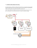
Wire AUTOPILOT and servo power circuits separately with their own fuse and switch:
AUTOPILOT, Flight Controller Power Module
and touchscreen (and optional TRIM system)
Switch and 5A fuse (or 10A w/ TRIM system)
Pitch and Roll Servos
Switch and fuse as per servo requirements
A backup power supply may be used and connected to the touchscreen micro USB connector.
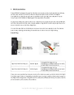
1.
AUTOPILOT
The optimal location for the AUTOPILOT is behind the instrument panel. (Make sure to leave
sufficient room for the USB connections).
The rectangular cut-out required will be approx. 3 inches x 2 1/4 inches (76mm x 57mm).
Metal instrument panels will require an insulated layer between the touchscreen display surface
and the panel for proper operation. The plastic frame of the case provided makes for a good
insulating layer. Simply remove the 4 screws, mount the AUTOPILOT behind the instrument panel
with the frame in place, and secure the AUTOPILOT with the screws from the front of the instrument
panel.
Overall dimensions of the AUTOPILOT
(Raspberry Pi) + Screen are approx. 4” (102mm) x 3” (76mm) x
1.5” (38mm)


