


Copyright © 2019 Xflight Technologies LLC, Florida, USA
3
6.
Safety Enable should already be connected from the Flight Controller to the Raspberry Pi
(AUTOPILOT) GPIO pins 32 & 30
7.
Servo Test Switch should already be installed in the Raspberry Pi (AUTOPILOT) GPIO pins 33 & 34
(this can be removed once calibration is complete)
8.
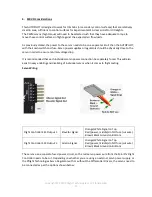
Connect the Wi-Fi module to the TELEM1 port of the Flight Controller
9.
Connect the TRIM system to the 5v power supply and to the Flight Controller
10.
Connect the yoke trim switches to the TRIM System (see details in section F)
11.
Make sure the SD card (AUTOPILOT software) is firmly seated inside the Raspberry Pi and the SD
card in the Flight Controller is also firmly seated (used for logging)
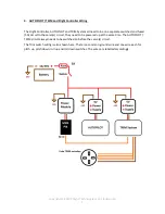
C.
Installation Overview
Additional details in section F.
1.
Mount the Flight Controller horizontally facing forward, sitting on a padded or foam base to
reduce vibration. (Adjustments for setting perfect level and for tail-wheel aircraft will be
covered later, under section G - Calibration).
2.
Mount the GPS antenna on the dash or somewhere with line of sight to the sky, facing forward.
3.
Connect the AUTOPILOT power supply and TRIM System power supply to the battery via a
separate switch and 10A fuse. Use a separate switch and fuse for the servo power circuits.
4.
When installing the AUTOPILOT behind the instrument panel, it is necessary to ensure there is
an insulated layer between the touchscreen display surface and the metal panel for proper
operation. The plastic frame of the case makes for a good insulating layer.


