


Copyright © 2019 Xflight Technologies LLC, Florida, USA
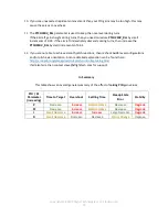
27
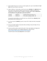
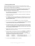
6. To remove the Test Switch:
Remove the autopilot from behind the instrument panel and remove the screen:
•
remove the 4 screws holding the frame to the screen (and instrument panel)
•
Remove the HDMI connector connecting the screen to the Raspberry Pi (this is very firmly
connected; some wiggling of the connector will be required)
•
Carefully lift the screen away from the Raspberry Pi (the black header pin block holds this to the
board)
•
The 40 header pins on the board should now be exposed
•
Remove the Test Switch jumper wires from pins 33 and 34, making sure to leave the Safety
Enable jumper wires attached to pins 30 and 32
•
Re-attach the screen to the header pins, ensuring correct alignment, and re connect the HDMI
connector
•
Re-install the AUTOPILOT behind the instrument panel.


