background image

V E R I C O L O R

®

  S P E C T R O  

                                                    7


Overview  

VeriColor Spectro Description 

The 

VeriColor

®

 Spectro 

is used to evaluate and identify colors in industrial applications. The 

VeriColor Spectro is a spectrophotometer that delivers 100% in-line, non-contact, absolute 
(L*a*b*) color measurement and identification. 
Like other color sensors, the VeriColor Spectro allows you to “learn” (measure) standard 
colors and measure samples for comparison. The system uses these comparisons to 

determine the closest standard or pass/fail a sample based on a tolerance. 
The system


is composed of two main components: the VeriColor Spectro which stores 

standard colors and captures sample color, and the software application. 


Unpacking and Inspection 

After removing the VeriColor Spectro from the shipping carton, inspect it for damage. If any 
damage has occurred during shipping, immediately contact the transportation company. Do 

not proceed with installation until the carrier's agent has inspected the damage. 
Your VeriColor Spectro was packaged in a specially designed carton to assure against 

damage. If shipment is necessary, the VeriColor Spectro should be packaged in the original 
carton along with all the accessories. If the original carton is not available, contact X-Rite to 

have a replacement shipped to you. 

Packaging Contents: 


VeriColor 

Spectro 


   P/N 

VS410-00-01 


5 Meter Male 8-Circuit Open Ended Cable    

P/N SE108-EUR8-5M 


5 Meter Female 8-Circuit Open Ended 


P/N VCS50-EUR8-5DB 


Calibration 

Tool 

    P/N 

VS410-63 


VeriColor Spectro Application Software CD  

P/N VS410-500-CD 


Setup and Operation Manual  


P/N VS410-500 


Registration Form (multi-language)  


P/N SD01-99 

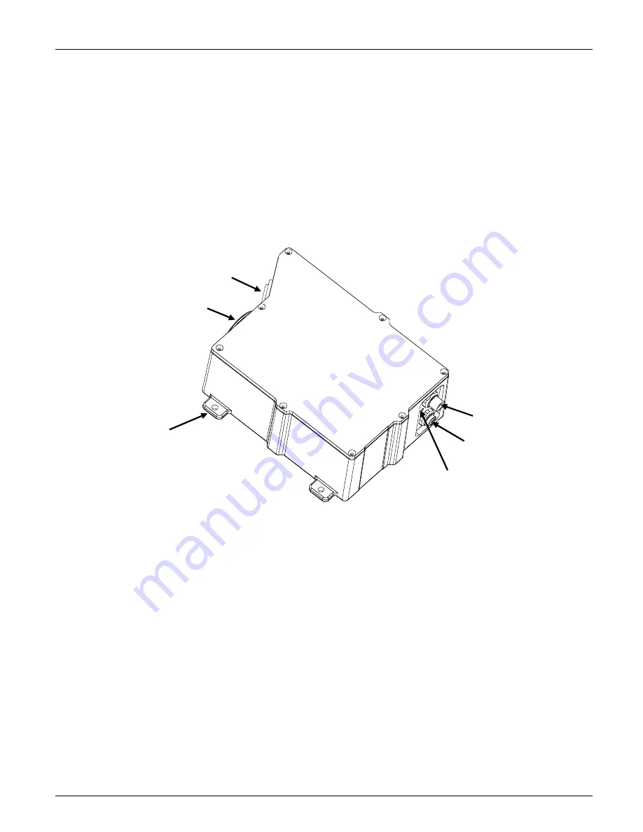
Sensor Lens 

Illumination Lens 

RS-232 Connector 

RS-485 /  PLC Connector

Status LED Indicator

Mounting Flange (4) 

Содержание VeriColor Spectro

Страница 1: ...VeriColor Spectro Non Contact Spectrophotometer Setup and Operator Manual ...

Страница 2: ......

Страница 3: ...rence to radio communications Operation of this equipment in a residential area is likely to cause harmful interference in which case the user will be required to correct the interference at his own expense Industry Canada Compliance Statement This Class A digital apparatus complies with Canadian ICES 003 Cet appareil numérique de la classe A est conforme à la norme NMB 003 du Canada Equipment Inf...

Страница 4: ...ach instrument manufactured to be free of defects in material and workmanship for a period of 12 months This warranty shall be fulfilled by the repair or replacement at the option of X Rite of any part or parts free of charge including labor F O B its factory or authorized service center This warranty shall be voided by any repair alteration or modification by persons other than employees of X Rit...

Страница 5: ... Options 20 Administrative Admin Setup 20 Language Tool 26 Targeting a Part 27 Calibration Verification of the VeriColor Spectro 28 Attaching the Calibration Tool 28 Performing Calibration first time out of box 29 Performing Verification 30 Performing Calibration after verification failure 31 Calibration Configuration 32 Color Standards and Projects 34 Creating Palettes and Color Standards 34 Veri...

Страница 6: ... O 6 General Maintenance 58 Repair Information 58 Cleaning the Spectro Instrument Lenses 58 Cleaning the Calibration Tool 58 Hardware Troubleshooting 59 Appendices 61 Specifications 61 Accessories 62 Electrical Interface Details 63 ...

Страница 7: ...ipping carton inspect it for damage If any damage has occurred during shipping immediately contact the transportation company Do not proceed with installation until the carrier s agent has inspected the damage Your VeriColor Spectro was packaged in a specially designed carton to assure against damage If shipment is necessary the VeriColor Spectro should be packaged in the original carton along wit...

Страница 8: ...ted in a 30 0 geometry alternate the distance is measured from the center of the sensor lens to the measurement surface CAUTION Keep the sensor lens and illumination lens free from dust smudge marks and finger prints 4 0 4 0 Sample Part Sensor Lens Illumination Lens Mounting Flange 4 0 30 Mounting Preferred 30 0 Mounting Alternate Sample Part Sensor Lens Illumination Lens Mounting Flange 4 IMPORTA...

Страница 9: ...964 or similar hand held spectrophotometer Other angles may be used example 7 5 37 5 but care must be taken to avoid sensing specular reflections from the illuminator Once the instrument has been trained on a sample in the preferred position it is critical that future samples be measured for comparison against the standard at the same measurement angle Any deviation in the measurement angle called...

Страница 10: ... S P E C T R O 10 VeriColor Spectro Dimension Drawing 200 07 mm 172 03 mm 25 29 mm 189 35 mm 227 20 mm 175 51 mm 67 05 mm 57 30 mm 31 90 mm 44 19 mm 98 47 mm 28 62 mm 6 35 mm 146 73 mm 73 30 mm 38 86 mm 0 76 mm 38 10 mm ...

Страница 11: ...es a Instrument power is applied via the white and brown wires 24 Vdc 2 Vdc IMPORTANT A limited current source must be used The applied operational power shall be a filtered 24 Vdc 2 Vdc tolerance having a 3 Amp capacity b RS232 communications is obtained via the pre wired DB9 connector c If manual or discrete operation is needed attach the appropriate wires to controlling device relay PLC termina...

Страница 12: ...tial between the controller and VeriColor Spectro is significant Power Comm Control Cable VCS50 EUR8 5DB 2 Negative brown 1 24 Vdc white 5 DSR gray 6 10 s pink 7 1 s blue 8 READ red Cable Shield Panel or fixture ground Discrete Interface Cable SE108 EUR8 5M 1 PASS white 2 FAIL brown 3 Output Comm green 4 CH E 16 ACTION yellow 5 CH D 8 RS485 TX A gray 6 CH C 4 RS485 RX A pink 7 CH B 2 RS485 RX B bl...

Страница 13: ... input request that allows the toggling of the 1 s and 10 s input so it must be activated first During the activation of DSR new measurement triggers are locked out ignored until DSR is completed Each time DSR is enabled the color number selection starts at 0 zero and increments according to the 1 s and 10 s toggling After the new color number has been selected when DSR is completed the new color ...

Страница 14: ...ground return for an external light or relay coil to turn on See Figure 1 Discrete I O Connections Example Low side output enable 1 2 5 3 8 7 6 4 2 8 24 Vdc Action Fail Pass brn red nu nu nu nu wht brn grn yel J1 Pwr RS232 male 8 pin J2 Discrete I O female 8 pin VC Spectro nu not used read Rx Rx Rx Rx current limiting resistor as needed Connector J2 Color Description Pin 1 White PASS pass result O...

Страница 15: ...common discrete outputs Output Pin 4 Yellow CH E ACTION result Output Instrument Outside Control Pin 5 Gray TXD A RXD A Output Pin 6 Pink RXD A TXD A Output Pin 7 Blue RXD B TXD B Output Pin 8 Red TXD B RXD B Output A B Figure 2 In the default project set up these wires are all discrete lines Pass Fail and ComO are always the same while CH A through CH D and Action can have an alternate configurat...

Страница 16: ...gray wire NOTE Connect the CH A RS 485 Tx A red wire and CH B RS 485 Rv A blue wire together for Half Duplex Also connect the CH C RS 485 Rv B pink wire and CH D RS 485 Tx B gray wire together for Half Duplex Computer Interface Normal computer communications between the user and the VeriColor Spectro is by the serial RS232 interface This interface is part of the Power Comm Control cable which has ...

Страница 17: ...lor Spectro located between the 2 rear mounted connectors is a LED indicator which visually provides system status This LED indicator is capable of displaying three colors green amber and red A description of each color status is listed below Off no color This generally indicates the VeriColor Spectro has no power Solid Green indicates the VeriColor Spectro is ready and waiting for further input d...

Страница 18: ...D ROM drive Browse to the Application folder and double click the setup exe file on the CD 2 The setup program guides you through the rest of the installation process Follow the instructions on each setup screen to complete the installation Starting the Application The software application can be launched using the VeriColor Spectro short cut on the desktop or from within the Programs VeriColor Sp...

Страница 19: ...r Spectro Admin used to configure the default settings for the application Setup used to create palettes and standards Application Modes Verify used to find the closest stored standard to a measured sample Project used to create projects Lookup used to auto select a standard from a palette Compare used to compare stored or measured trial and standard data Monitor used to monitor sample measurement...

Страница 20: ...r of days that pass before you would like to be reminded to perform a verification Use the up down arrows to select the number of days ranging from 1 to 30 The default number is 1 3 Click one of the Baud Rate buttons to select the desired baud rate Once selected the instrument and software will both be configured The default baud rate is 115200 You can click the Test instrument button to check the...

Страница 21: ...the measurement will be triggered measurement interval time for timed interval and the Tolerance dE value used for Verify mode 1 Select Manual Timed interval or External Trigger as the trigger mode This determines the measurement method that is used in Verify mode The default mode is Timed interval Manual selection requires a Measure button click for each measurement Timed interval allows automati...

Страница 22: ...e and averaging number used for Lookup mode 1 Click in the Tolerance dE cmc field and enter desired tolerance value This determines the dE cmc value used in the Lookup mode 2 Click the OK button to save your setting and exit Admin or select the General Verify Compare or Monitor page to continue with option settings ...

Страница 23: ...he Operator field s and enter the desired name s This establishes a list of operators that can be selected from in the Compare mode 3 Click in the Title Company Street and Town fields and enter appropriate information This determines the information that will be printed in a Compare report Checking with mean value causes the average values to also print on the report 4 Click the OK button to save ...

Страница 24: ...used the condition scrolls from the screen in the trend graph Note When unchecked the alert level will also increase if applicable warning to fail Refer to Viewing Sample Data in the Monitor Mode section for additional information 3 Check Auto Target from Project to automatically search the database for a standard that more closely matches the sample measurement Search criteria is set by entering ...

Страница 25: ...V E R I C O L O R S P E C T R O 25 SAMPLE LOG REPORT ...

Страница 26: ...mn on the left is the reference column and cannot be edited The column on the right is the column that is used to localize the text strings 2 Translate the text in the column on the right and then select another form 3 Click the Test in Form button to view the translation made to the application without saving them 4 Click the Save to file button to save the localized text strings to the applicati...

Страница 27: ... at 30 0 approximately 1 00 in diameter begins flashing This is the VeriColor Spectro s measurement viewing area You can turn the targeting light off or on by clicking the appropriate button 3 Without disturbing the pre aligned height and position of the VeriColor Spectro carefully adjust the VeriColor Spectro x and y coordinates so the red circle is centered on the area of the part you wish to me...

Страница 28: ...ed with your VeriColor Spectro is configured for that specific instrument If a replacement calibration tool is used you will need to reconfigure the instrument for that replacement tool Refer to Calibration Configuration later in this section for details on reconfiguring for a new calibration tool Attaching the Calibration Tool IMPORTANT Do not touch the white reference in the bottom of the calibr...

Страница 29: ...iously explained When tool is properly attached click the OK button on the attach calibration tube screen The instrument takes five calibration measurements 5 Click Exit on the Calibration dialog 6 Remove the calibration tool and place in its storage bag NOTE If an error message appears after calibration make sure the calibration tool is located correctly over the illumination lens and is clean Yo...

Страница 30: ... to the Cleaning section later in this document and then click OK on the Insure lenses are screen 4 Attach the calibration tool as requested Refer to Attaching the Calibration Tool as previously explained When the tool is properly attached click the OK button on the attach calibration tube screen The instrument takes one measurement updates the White Verification Difference value and the Last Veri...

Страница 31: ...reviously explained When the tool is properly attached click the OK button on the attach calibration tube screen 4 The instrument takes five calibration measurements and updates the Last Calibration Time stamp 5 Click OK on the Calibration Ok screen 6 Remove the calibration tool and place in its storage bag NOTE If an error message appears after calibration make sure the calibration tool is locate...

Страница 32: ... Verification Tolerance The tolerance value entered is used to determine the verification difference tolerance The default value is set to 1 00 1 Click in the White Verification Tol field and edit the value 2 Click the Load New Values button to download to the instrument 3 Click the Close button to close the Configuration Calibration Values dialog Selecting the Mounting Geometry This option is use...

Страница 33: ...lacement calibration tool Editing the White Calibration Plaque Values for non X Rite calibration reference If desired you can use a non X Rite calibration reference with the VeriColor Spectro Values assigned to the reference must be entered into VeriColor Spectro via the software application The calibration plaque values list all wavelength values for the current old plaque The old values are also...

Страница 34: ...ing it is best to create the standard in this dynamic environment It is recommended that the standard be created based on the average of a series of multiple measurements 5 10 Creating Palettes and Color Standards The Setup mode is used to create and edit standards and palettes A palette is used for grouping color standards The Setup dialog is accessed by clicking the Setup menu item at the top of...

Страница 35: ... to take the measurement 6 Take additional measurement if averaging is used for the color standard 7 Click the Save button to save the standard to the database and return to the main Setup dialog The color standard number measurement time stamp simulated color and data values are displayed below the name 8 If required enter specific tolerance values other than the default values for the standard R...

Страница 36: ...ng toward a fail condition but still is within the defined tolerance You can select between 25 and 99 as a action limit percentage This percentage is applied to the upper and lower user defined tolerances in L a b L c h dEcmc and DE EXAMPLE If the tolerance for a standard is 1 00 dE on L a and b setting the action limit to 75 will activate the yellow warning light if the standard drifts to or abov...

Страница 37: ...s the current standard in the field The same control can be used to select a different standard if more than one exists 5 Standards field lists the number of standards that exist in the selected palette 6 Edit Standard button is used to edit the name or measured data of a standard You would first select the standard from the Choose Standards list to edit and then click the Edit Standards button 7 ...

Страница 38: ...d save the data to an Excel master csv file Any new measurements that you want to add to the master file should be saved in a new file The data is then selected from the new file and then copied into the master csv 2 Delete any data not needed in the master file and then average the R values 3 Once averaged copy the reflectance values into fields B1 through AF1 of the NewImport csv file located on...

Страница 39: ...l sample measurements Set the amount of time in the Interval fields using up down arrows Time intervals can range from 2 second up to 60 minutes 4 Position the color standard under the VeriColor Spectro as specified earlier 5 Perform targeting if required refer to Targeting a Part earlier in this section and then click the Measure button on the Verify dialog to take the measurement The closest col...

Страница 40: ...dependent of the software application The Project dialog is accessed by clicking the Project button at the bottom of the application 1 Select the palette where your color standards are stored from the Palette pull down list Color standards from the selected palette appear in the Standards numbered list on the left side of the screen 2 Click the New project button enter a project name and click OK ...

Страница 41: ...n the instrument will be deleted Click Yes to continue 6 When you have finished creating project click the Close button to return to the main application screen Additional Project Dialog Controls 1 Upload project from instrument button is used to retrieve the project currently stored in VeriColor Spectro The retrieved project name and standards will appear in the list on the right side of the scre...

Страница 42: ...omatically transmitted after a measurement When set to OFF default setting no data is automatically transmitted after a measurement When set to ON you would choose what data is transmitted Select Status only LabCh Smp LabCh Std Dif Refl Smp or Refl Smp Std option for the type of data to transmit Output Allows you to select an instrument configuration that dedicates the outputs of channels A E to s...

Страница 43: ...ult setting or adjusted from 2 to 10 measurements to average Time delayed between measurements can be set from 0 to 10 seconds When the control is set to 0 the Measure button must be clicked to take the measurement When set to a time increment 10 1 sec 20 2 sec etc the instrument will pause the defined amount between measurements PLC Determines the amount of time the instrument will pause after se...

Страница 44: ...first step is to select a target standard or measure a target standard If Auto Target was setup in the Admin Monitor page you would select the project where the standards are located If auto targeting is not used you would select a specific target Selecting a Single Standard no auto target 1 Click the Target from file button to open a dialog where a stored standard is selected as the target color ...

Страница 45: ...aken 1 Click the Target from file button to open the Standard from file dialog 2 Note that the Palette list and Project list are disabled on this dialog Select the standard from the as standard list 3 Click Choose to select the standard and close the Standard from file dialog The standard name appears in the Target field and the data values and tolerances appear below that Auto Target appears to t...

Страница 46: ...Tolerances that were created for a standard opened from the file will be carried over You can edit these tolerances without overwriting the stored tolerance values 1 Click in the Tolerance button to open the dialog where the tolerances are edited 2 Select the desired tolerance from the Type of Tolerance list 3 Enter tolerance values in the available fields and adjust the Action limit if required 4...

Страница 47: ...t name changes to Mean and indicates the number of samples measured to obtain an average IMPORTANT If you choose your standard from file and then change the standard to the mean average of the series of measurements the tolerances that carried over from the standard from file will no longer apply You will need to manually adjust the tolerance to compensate for the difference in the current mean av...

Страница 48: ...usly explained and prepare the samples for measurement 2 Determines the amount of time that needs to elapse between timed interval sample measurements Set the amount of time in the Interval fields using up down arrows Time intervals can range from 2 second up to 60 minutes 3 If desired set the Averaging Samples or Sliding Averaging from 1 no averaging to a maximum of 20 using the up down arrows Sl...

Страница 49: ...ference data by clicking between the abs and dif buttons Trend Graph and Controls The trend graph displays the pass warning fail status of the last 25 sample measurements Graph bars represents individual measurements or averaged measurements if sliding averaging is used Upper and lower Action and Fail limit lines display as yellow and red respectively only on applicable tolerance options correlati...

Страница 50: ...nt is within tolerance and is a pass The yellow light indicates that the measurement is trending toward a fail condition but is still within tolerance And the red light indicates the measurement is outside of tolerance and is in a fail condition Any pre set attribute that is out of tolerance will cause a fail condition Pass green Warning yellow Fail red The traffic light reacts differently based o...

Страница 51: ...r more and Only Last Record for PASS FAIL disabled unchecked Green light all of the grouped measurement averages displaying within the active trend graph window are passing Yellow light one or more of the grouped measurement averages displaying within the active trend graph window has triggered the warn condition action limit Yellow will continue to display until the measurement group average that...

Страница 52: ...ed by clicking the Lookup button at the bottom of the application 1 Click in the Target field and enter a name for the sample to be measured 2 If desired set the Averaging Target from 1 no averaging to a maximum of 20 using the up down arrows This determines the amount of measurements required to obtain an average in Lookup mode 3 Prepare the sample for measurement 4 Perform targeting if required ...

Страница 53: ... results click the Print button A report that includes the measurement data for the measured target and all the standards will be sent to your default printer Sample Lookup Report 6 When you have finished with the Lookup mode click the Close button to return to the main application screen ...

Страница 54: ... project The Compare dialog is accessed by clicking the Compare button at the bottom of the application 1 Select the operator that will be running the compare from the Operator drop down list The operator names listed are entered in Compare options page of the Admin dialog 2 Enter required information in the two fields below the operator s name In the dialog above they are Lot ID and Serial ID The...

Страница 55: ...in an average 3 Perform targeting if required refer to Targeting a Part earlier in this section and click the Measure standard button If a previous standard exists you will be asked if you want to overwrite the current standard Click Yes to continue The standard is measure and the data and simulated color appear in the target area 4 Enter a name for the standard in the Std field Setting Tolerances...

Страница 56: ...splays the mean values of all the selected trials Measuring a Trial 1 Prepare the trial for measurement and perform targeting if required refer to Targeting a Part earlier in this section 2 Click the Measure trial button The trial is measured and the data and simulated color appear in the target area 3 Enter a name for the trial in the Trial field 4 Click the abs or dif buttons to display trial da...

Страница 57: ...ndards and trial data to the default printer Refer to the next page for a sample print out Save button is used to save the standard and sample measurement data in a txt csv or mif file format Close button closes the Compare dialog and returns you to the main application screen Sample Compare Report ...

Страница 58: ...id by the customer Cleaning the Spectro Instrument Lenses Normally use low pressure air to blow away any dust or debris on the lenses or use a soft lens brush To remove dirt or finger prints clean with a soft cotton cloth rubbing in a circular motion Use of a coarse cloth or unnecessary rubbing may scratch the lens surface and eventually cause permanent damage For a more thorough cleaning photogra...

Страница 59: ...put does not work system does not measure LED indicator light does not work solid amber with input Instrument may have just powered up and is still trying to initialize flashing amber Wait until the VeriColor Spectro indicates a solid green before attempting to measure Terminal screws not tightened firmly on wires or loose or broken wires Providing DC voltage or otherwise to the input is not corre...

Страница 60: ... for electrical wiring diagram Contamination has entered the terminal and is preventing a reliable connection Go over the entire system looking for loose or obviously damaged cables A cable that is shorted out can cease all communications Instrument will not communicate Check cables first It might be a quick fix and are the cheapest parts to replace A cable that is loose might cause intermittent c...

Страница 61: ... 22 86 cm 9 in W 15 3 cm 6 in H 7 62 cm 3 in Weight 2 81 kg 6 2 lbs Mounting Requirements Manual Fixture Enclosure Designed to meet NEMA 4 IP56 Performance Warm up Time 2 3 min typical at 23 C 73 4 F Measurement Time 750 ms Cycle Time 1 sec time interval between measurements Ambient Light Rejection 3000 Lux Short Term Repeatability 0 03 avg 0 05 max ΔEab 20 measurements at 3 sec intervals on a whi...

Страница 62: ...tions subject to change without notice Accessories The following accessory items can be purchased from X Rite by calling 1 888 826 3042 or by visiting our website at www xrite com 5 Meter Female Open Ended Cable 8 circuit DB9 P N VCS50 EUR8 5DB 5 Meter Male Open Ended Cable 8 circuit P N SE108 EUR8 5M 1 Meter Interconnect Cable 8 circuit P N SE108 EUR8 1 3 Meter Interconnect Cable 8 circuit P N SE...

Страница 63: ...V max 12V min rating 100mA max 8 J1 8 Read Take a Measurement High 50 msec pulse DSR must be active to work Input 24V max 12V min rating 100mA max Cable Shield Shield Connect to the panel or fixture ground Discrete Interface Cable Item Pin Name Default Option see Note 2 Description Active State Comments 1 J2 1 Pass Pass Pass output See Note 3 2 J2 2 Fail Fail Fail output See Note 3 3 J2 3 Output C...

Страница 64: ... are low power outputs which use a common control line referenced ComO the green wire This common line is either a supply or ground return connection for these outputs a Low power means these outputs can only handle up to 24Vdc at 80 milliamps max b All outputs default as normally open contacts but can be configured as to normally closed contacts Note they still all use a common control line c If ...

Страница 65: ......

Страница 66: ......

Страница 67: ......

Страница 68: ...6 803 2705 Corporate Headquarters Europe Althardstrasse 70 8105 Regensdorf Switzerland Phone 41 44 842 24 00 Fax 41 44 842 22 22 Corporate Headquarters Asia Room 808 810 Kornhill Metro Tower 1 Kornhill Road Quarry Bay Hong Kong Phone 852 2 568 6283 Fax 852 2 885 8610 Please visit www xrite com for a local office near you P N VS410 500 Rev B ...

Отзывы: