31
1. Use the wall-mount bracket as a template to determine the positions of the
mounting holes on the wall.
2. Mark the locations of the mounting holes.
Note
When determining location, take into account the cable
lengths of the monitor, keyboard, mouse, power supply,
and peripherals.
3. Install the (user-provided) wall anchors. Any standard anchoring method may be
used, such as screws, butterfly anchors, or expansion bolts. The anchor screw
heads must have just enough clearance to allow the bracket to slip onto them
when hanging the assembled terminal (see the Caution above).
4. Loosen (but do not remove) the two screws securing the mounting clips to the
back panel. Leave enough clearance so the lower tabs of the mounting bracket
can slip under the screws.
5. Insert the upper tabs of the mounting bracket into the slotted holes in the back of
the terminal housing.
6. Slip the lower tabs of the mounting bracket under the two screws loosened in
step 4. The tabs should go between the screw heads and the mounting clips.
7. Tighten the screws to hold the bracket firmly in place.
8. Hang the terminal assembly on the wall-anchor mounting screws.
9. Install the cable retaining loop and shroud using the procedure that follows.
Optional Cable Retaining Clip and Shroud Installation
An optional plastic shroud may be installed to conceal the cable connectors at the
rear of the terminal housing. A retaining loop is included to keep the cables
together. Proceed as follows.
1. Attach the upper and lower shroud mounting clips as shown in Figure 4-5, using
the existing screws.
2. Attach the cables to their respective connectors on the back panel of the
terminal (see “Connecting the Terminal”).
3. Gather the cables together and place the retaining loop over them. Insert the
ends of the retaining loop into the catches on the lower shroud mounting clip
(see the following figure).
Содержание Winterm 3200LE
Страница 1: ...Winterm 3000 Series Windows based Terminal Administrators Guide ...
Страница 2: ......
Страница 4: ......
Страница 32: ...xxx ...
Страница 34: ...2 ...
Страница 38: ...6 Terminal Installation ...
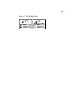
Страница 73: ...41 Figure 5 4 3720SE Recall Mode R G B 9300 K 1 2 3 R G B USER 1 1 2 3 RECALL 9300K ...
Страница 74: ...42 Terminal Installation ...
Страница 76: ...44 ...
Страница 102: ...70 Advanced User Interface Figure 9 1 Apps Properties Sheet SE Model Terminals ...
Страница 116: ...84 Advanced User Interface ...
Страница 118: ...86 ...
Страница 122: ...90 Connection Configuration ...
Страница 132: ...100 Connection Configuration ...
Страница 148: ...116 Connection Configuration Figure 16 1 Script Name Dialog Box Figure 16 2 New Script Name Dialog Box ...
Страница 156: ...124 Connection Configuration ...
Страница 164: ...132 Connection Configuration ...
Страница 172: ...140 Connection Configuration ...
Страница 188: ...156 Connection Configuration ...
Страница 190: ...158 ...
Страница 196: ...164 External Devices ...
Страница 202: ...170 External Devices Figure 24 1 Add or Change Modem Dialog Box Table 24 1 discusses the functions of this dialog box ...
Страница 206: ...174 External Devices ...
Страница 217: ...185 Figure 26 2 Printers Properties Sheet ...
Страница 220: ...188 External Devices ...
Страница 232: ...200 ...
Страница 238: ...206 Firmware Upgrades ...
Страница 250: ...218 Firmware Upgrades ...
Страница 256: ...224 Firmware Upgrades ...
Страница 258: ...226 ...
Страница 264: ...232 Security Properties ...
Страница 272: ...240 Client Security ...
Страница 286: ...254 ...
Страница 294: ...262 Getting Help ...
Страница 304: ...272 Getting Help ...
Страница 306: ...274 Getting Help ...
Страница 310: ...278 Getting Help ...
Страница 344: ...Glossary 312 ...
Страница 351: ...Index 319 ...


