5
3.8. POSITIONING THE FLUE SYSTEM
It may be necessary to deviate from the following method of
installation because of site conditions. However, joints must
be sealed and fixed as described.
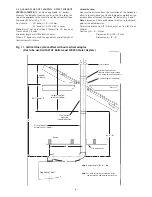
Align the centre of the flue spigot with the ceiling and mark
the centre position. Refer to Fig. 8. Cut a hole 175mm (7in.)
diameter in the ceiling.
Working within the roof space repeat the procedure and mark
the centre position of the flue on the inside surface of the roof.
Mark a 125mm diameter circle on the inside surface to
represent the outside diameter of the flue. Refer to Fig. 8.
This procedure is the same for flat and pitched roofs.
Important: The terminal assembly must extend at least
300mm above the surface or pitch of the roof. The distance
may vary depending upon the type of roof and surrounding
structures. In these instructions the distance is refered to as
dimension 'F'. Refer to Fig. 9.10.11.12.
Fig. 8. Marking out the flue assembly position.
Vertical Flue System (no offset)
Appliance
front
Appliance
front
Vertical Flue System (with an offset)
Flue centre position
on top of appliance
Using a plumb line, align the centre of
the flue spigot or offset duct with the
ceiling and roof. Mark the roof with the
centre position of the flue and draw a
circle 125mm (5in.) dia. on the inside
of the roof.
Offset section
Plumb-line
Plumb-line
Ceiling
Pitched roof
Pitched roof
Flat roof
Flat roof
Ceiling
175mm (7in.) dia. hole in ceiling


