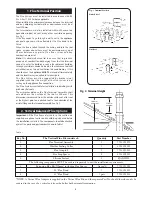
8
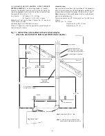
4.3 AIR AND FLUE DUCT LENGTHS - OFFSET WITHOUT
VERTICAL ADAPTER
(90° or, where applicable, 45° bends)
Measure the distance from the centre of the flue spigot on
top of the appliance to the centre line of the vertical sections.
Dimension
D.
Refer to Fig. 11,12.
Duct Length:
90° bends =
D
— 162mm
45° bends = (1.414 x
D
) — 60mm
Note:
D must not be less than 210mm with 90° bends or
76mm with 45° bends.
Minimum length of air/flue duct is 48mm.
When 45° bends are used the equivalent overall height of
that section is D+60mm.
Vertical Section:
Measure the distance from the centre-line of the horizontal
offset to the outside edge of the hole diameter marked on the
inside surface of the roof. Dimension '
K
'. Refer to Fig. 6 and 7.
Note:
Dimension K For a pitched roof must go to the highest
point of the hole diameter.
Determine dimension '
F'
which must not be less than
300mm.
Duct Length =
L
— 81mm
Dimension
G
=1100 —
F
mm
Dimension
L
=
K
—
G
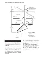
Air inlet flange
Weather sealing collar
(Secure with screw provided
and seal with silicone sealant)
Roof flashing (not supplied)
Flat roof
Pitched roof
Ceiling
Fire stop spacer
Note:
Straight length (
D
+
L
) - 250
Note:
For more information on bends in flue
see installation and service instructions.
90° flue bends
Appliance front
300mm
minimum
Height of terminal
assembly 1100mm
Flue terminal
assembly
(106mm diameter)
G
= 1100mm -
F
Air and flue duct
extension kits (750mm)
F
K
D
L
=
K
-
G
Fig. 11. Vertical flue system offset without vertical adaptor
(Not to be used with WH1 Boilers and WR325 Water Heaters)


