15.22 Air pressure Switch
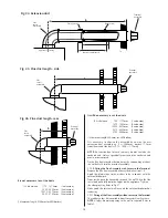
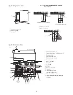
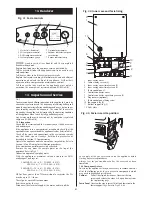
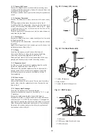
The air pressure switch is held in position by a fixing bracket. In
order to remove the switch:
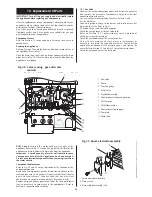
Gently move outwards the securing clips holding the switch to
the bracket.
Remove the air pressure tubes and wires from the switch.
Push the replacement switch, with the tube connectors pointing
forwards, into the bracket and then replace the wires and pres-
sure tubes.
If the fixing bracket needs replacing, remove the switch as
described above then remove the two screws holding the bracket
to the top of the appliance. Refer to Fig 63 and 64.
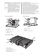
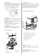
15.23 Sight Glass
Remove and replace the inner casing cover complete.
Refer to Section 14.3, Inspection and Servicing. Refer to Fig 42.
29
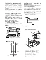
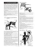
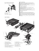
Fig. 62. Primary heat exchanger
1
2
3
4
5
6
1. Heat exchanger
2. CH flow/return pipes
3. DHW inlet/outlet pipes
4. Seal
5. Overheat thermostat
6. Primary sensor
Fig. 64. Air flow pressure switch
1
2
3
4
5
1. Electrical connections
2. Air pressure switch
3. Screws
4. Air pressure switch fixing clip
5. Securing clip
6. Tube connectors
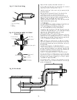
Fig. 63. Air flow pressure switch location
3
6
5
4
1. Air pressure switch
2. Fixing bracket
3. Air pressure switch
fixing clip
1
4. Combustion sensing
point location
5. Negative pressure tube (–)
6. Positive pressure tube (+)
2
6
+Ve
—Ve

