9
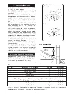
Air inlet flange
Weather sealing collar
(Secure with screw provided
and seal with silicone sealant)
Roof flashing (not supplied)
Flat roof
Pitched roof
Ceiling
Fire stop spacer
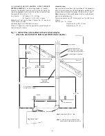
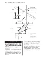
Note:
45° bends may be applied
in any system layout as with
90° bends.
Note:
For more information on
bends in flue see installation
and servicing instructions.
45° flue bends
Appliance front
300mm
minimum
Flue terminal assembly
(106mm diameter)
F
G
= 1100mm -
F
Height of offset
=
D
+ 60mm
(1.414 x
D
) - 60
K
Height of terminal
assembly 1100mm
L
=
K
-
G
D
Fig. 12. Vertical flue system (offset with 45° flue bends)
5.1 It may be necessary to deviate from the following
method of installation because of site conditions,
however, the joints must be sealed and fixed as described.
5.2 CUT DUCTS
When measurements have been made and
checked
, cut the
air and flue ducts to length ensuring that the cuts are square
and free from burrs.
All dimensions refer to straight lengths and do not include
the expanded ends. Do not cut the expanded ends unless
specifically instructed to do so.
5.3 POSITION OF THE FIRE STOP SPACER ASSEMBLY
Fit the fire stop spacer centrally over the hole in the ceiling.
Ensure the hole aligns with the flue spigot on top of the
appliance casing.
5. Installation of Flue
Mark the four fixing hole positions in each half for No.10 x
30mm wood screws (not supplied) and fix either into the
existing joists or into reinforcement nogs. Alternatively, the
plate may be fixed to the ceiling using plasterboard toggle
screws. Refer to Fig. 7.
5.4 POSITION OF THE FLUE DUCT SUPPORT BRACKET
From inside the roof space fit the support centrally over the
hole in the ceiling. Ensure the hole aligns with the fire stop
spacer and flue spigot on top of the appliance casing.
Mark and fix into position as previously described for the fire
stop spacer. Refer to Fig. 6.
Remove the fire stop spacer and support bracket until the
flue is assembled.

