Operation Manual 37107F
MFR 3 - Multi Function Relay
© Woodward
Page 75/165
NOTE
The following settings in the n/f controller area affect the P controller.
Parameter
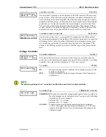
42
F/P contr.type
----------------
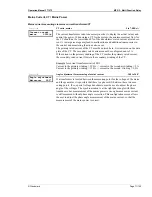
f controller: type
THREESTEP / ANALOG / PWM
THREESTEP
The signal to control the speed/frequency/real power is output via
the relay manager to any configured relay. You can use the following
parameters of the relay manager:
parameter 99 = n+/f+/P+
parameter 100 = n-/f-/P-
ANALOG
.... Control is performed via the analog controller outputs to terminals
8/9/10. The signal selection is made in Parameter 46 "F/P contr. out-
put" and though the use of an external jumper depending on the con-
figured signal.
PWM
........... The control of speed/frequency/real power is performed via a PWM
signal. The signal amplitude is set in Parameter 47 "Level PWM". An
additional jumper must be added.
Three-Position Controller (Setting THREESTEP)
Parameter
43
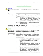
Freq.controller
dead band 0.00Hz
f controller: dead band
0.02 to 1.00 Hz
Isolated operation
The generator frequency is controlled in such a manner, that in
a steady state, the actual value does not deviate from the generator
frequency set point by more than the configured dead band value.
Synchronization
The generator frequency is controlled in such a manner, that in
its steady state, the differential frequency does not exceed the confi-
gured dead band value. The mains or busbar frequency is used as the
set point value.
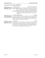
Parameter
44
Freq.controller
time pulse>000ms
f controller: minimum ON period
10 to 250 ms
The minimum ON period of the relay should be selected in such a manner that the
speed governor responds reliably to the control pulse. The time configured here de-
termines the length of the control pulse. The smallest possible time must be confi-
gured in order to ensure optimum control behavior.
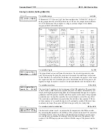
Parameter
45
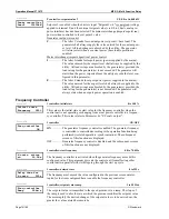
Freq.controller
gains.Kp 00.0
f controller: gain
0.1 to 99.9
The gain factor K
P
indicates the frequency controller gain. By increasing the gain
factor, the response is increased to permit larger corrections to the variable to be
controlled. The farther out of tolerance the process is the larger the response action
is to return the process to the tolerance band. If the gain is configured too high, the
result is excessive overshoot/undershoot of the desired value.


