


Operation Manual 37107F
MFR 3 - Multi Function Relay
Page 56/165
© Woodward
Introduction
≡≡≡≡≡≡≡≡≡≡≡≡≡≡≡≡≡≡≡≡≡≡≡≡≡
The configuration screens have an AUTOROLL function when you are in configuration mode (simultaneously
pressing "Digit
↑
" and "Cursor
→
"). If the "Select" button is pressed and held, the scroll function will be activated
and the user will be able to rapidly advance through the parameter screens. It is possible to back-up four configu-
ration screens (exception: the break from the first to the last screen is not possible). To do this, simultaneously
press and release the "Select" and "Cursor
→
" buttons. If an action, entry, or modification, is not performed with-
in 60 seconds, the unit reverts to the automatic mode.
NOTE
There are two different hardware versions described in this manual: A 100 Vac version [1] and a
400 Vac version [4]. The two versions vary as far as the configuration screens, the input of the parame-
ters and the setting limits are concerned. The respective voltage values ([1]... or [4]...) are placed first to
differentiate the two types.
Basic Data
≡≡≡≡≡≡≡≡≡≡≡≡≡≡≡≡≡≡≡≡≡≡≡≡≡
Language Manager
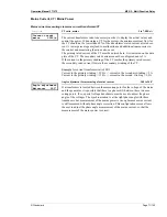
Parameter
1
Sprache/language
----------------
Language first/second
first
............... All texts are displayed in the base/first language.
second
........... All texts are displayed in the second language.
Parameter
2
Load language
YES
Load language
YES/NO
YES
.............. A language file may be loaded if code level 2 has been activated.
NO
................ Language loading capabilities are disabled. The following related
configuration screens are not displayed.
Parameter
3
Language number
0
Language selection
0/1
The number entered here determines if the first or second language is to be loaded.
0
.................... The base/first language is to be loaded.
1
.................... The second language is to be loaded.
Parameter
4
Number of tool
00
Unit number on the CAN bus
1 to 14
If the control unit language is being modified over the CAN bus, the assigned unit
number must be entered here. If the control unit language is being modified via the
DPC, it is not necessary to enter a value in this screen (refer to next parameter).


