Operation Manual 37107F
MFR 3 - Multi Function Relay
© Woodward
Page 65/165
Voltage Transformer, PTs
CAUTION
If the following parameter values are modified, the values of the following parameters must be verified:
•
generator voltage set point (at page 66)
•
voltage controller dead band (at page 77)
•
synchronization dVmax (at page 91)
•
dead bus start GCB dVmax (at page 93)
•
generator overvoltage tripping value (at page 109)
•
generator undervoltage tripping value (at page 110)
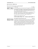
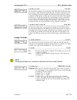
Parameter
15
Gen.volt.transf.
secondary 000V
PTs, secondary, generator
[1] 50 to 125 V; [4] 50 to 480 V
The secondary voltage is set here in V. This is the voltage level that will be meas-
ured at the control unit input terminals.
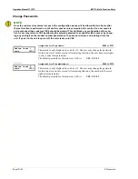
Parameter
16
Gen.volt.transf.
primary 00.000kV
PTs. primary, generator
[1] 0.005 to 65,000 kV; [4] 0.020 to 65,000 kV
The primary voltage is set here in kV. This entry serves to indicate the primary vol-
tages in the display. If a potential transformer is not used, the measured voltage of
120V would be configured as "
00.120kV
" and 480V would be configured as
"
00.480kV
".
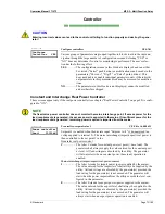
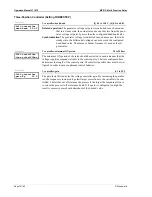
Parameter
17
Bus.volt.transf.
secondary 000V
PTs, secondary, busbar
[1] 50 to 125 V; [4] 50 to 480 V
The secondary voltage is set here in V. This is the voltage level that will be meas-
ured at the control unit input terminals.
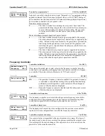
Parameter
18
Bus.volt.transf.
primary 00.000kV
PTs, primary, busbar
[1] 0.005 to 65,000 kV; [4] 0.020 to 65,000 kV
The primary voltage is set here in kV. This entry serves to indicate the primary vol-
tages in the display. If a potential transformer is not used, the measured voltage of
120V would be configured as "
00.120kV
" and 480V would be configured as
"
00.480kV
".


