


Operation Manual 37107F
MFR 3 - Multi Function Relay
© Woodward
Page 17/165
G
4
0 Vdc
2005-10-10 | MFR 3 Packages Wiring Diagram r3ww-4105-ap.skf
9
6
7
8
A
B
C
50
51
52
27
28
40
16
17
53
54
23
24
41
14
15
3
25
26
39
42
29
30
31
32
20
21
22
11
12
13
8
9
10
105
10
6
10
7
10
8
10
9
11
0
111
11
2
11
3
X1
X2
X3
X4
X5
13
0
13
1
13
2
13
3
0
1
2
5
6
7
33
34
35
36
60
61
62
63
64
65
66
67
68
69
70
71
72
73
18
19
74
75
76
77
78
79
80
81
82
83
93
94
95
96
97
98
99
10
0
10
1
10
2
10
3
104
GND
s2 (l)
s1 (k)
L1
L2
s2 (l)
s1 (k)
s2 (l)
s1 (k)
s2 (l)
s1 (k)
GND
A
I
A
I
12/24 Vdc
N
raise
lower
R
ela
is
m
an
ag
er
(fr
ei p
ro
gr
am
m
ie
rb
ar
e R
ela
is
)
up
to 14 add
iti
onal
ge
ne
rat
or
s
(each
vi
a
one
M
FR
3)
GA
T
E
W
AY
GW
4
C
on
tro
l ro
om
SPS PC
Dr
iv
e
Mains current L1
Subject to technical mocifications.
Mains voltage L1
Mains voltage L3
Mains voltage L2
Busbar voltage
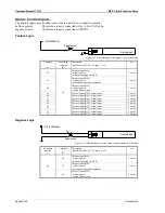
Enable GCB
raise
lower
Ready for operation
Switch setpoint 1 <--> 2
Enable monitoring
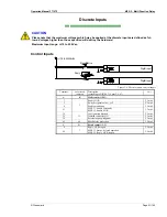
Common (terminal 3/4/5/6/53/54)
Common
Configuration blocked
Isolated operation controller ON
External acknowledgement
Common
Blocking of mains protection
Alarm input [D04]
Alarm input [D06]
Alarm input [D07]
Alarm input [D08]
Alarm input [D09]
Alarm input [D10]
Alarm input [D11]
Alarm input [D12]
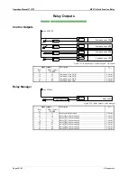
Relay [R1]
Relay [R2]
Relay [R3]
Relay [R4]
Relay [R5]
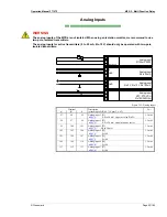
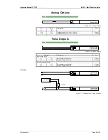
Analog input 1 [T1]
0/4 to 20 mA
- Setpoint: Real power kW
Analog input 2 [T2]
0/4 to 20 mA
- Setpoint: power factor
Analog input 3 [T3]
0/4 to 20 mA
- Alarm input
Analog input 4 [T4]
Pt100
- Alarm input
Command: open GCB
Generator current L1
Generator current L2
Generator current L3
Generator voltage L1
Generator voltage L2
Generator voltage L3
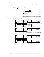
SPEED / POWER
(three-position controller)
or
Analog controller output
VOLTAGE / POW. FAC.
(three-position controller)
or
Analog controller output
Analog input 5 [T5]
Pt100
- Alarm input
Analog input 7 [T7]
Pt100
- Alarm input
Analog input 6 [T6]
Pt100
- Alarm input
Analog output
0/4 to 20 mA
Command: close GCB
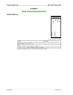
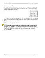
Th
e
so
ck
et
for
the PC
c
onf
igu
ra
tion i
s s
itua
ted on t
he
si
de of
th
e
uni
t.T
hi
s
is
w
he
re t
he
DPC
has
to
be
p
lugg
ed
in.
Reply: MCB is open
Command: close MCB
Enable MCB
Command: open MCB
M
F
R
3
2 (
M
ul
ti
Fun
ct
ion
R
el
ay)
CAN bus interface
Guidance level
GND
CAN-H
CAN-L
Termination
Relay [R6]
38
37
Relay [R7]
48
47
Alarm input [D03] or
Switch breaker logic
3
Alarm input [D02] or
Operation mode selector locked
2
Alarm input [D01] or
Mains decoupling via MCB
1
5
Alarm input [D05]
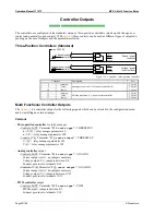
Impulse output kvarh
Open collector
Impulse output kWh
Open collector
13
4
13
5
136
13
7
conf
ig
ur
abl
e du
rin
g se
tu
p (
N
O
/N
C
)
#1
#1
Ba
tter
y or
a
not
her
powe
r
sup
pl
y;
ter
m
inal
6
0 i
s
po
s.
or
ne
g.
si
gn
al
#2
NO/
NC
Battery
#2
#2Battery
Battery
#2
#1
NO/
NC
#1
NO/
NC
#1
NO/
NC
#1
NO/
NC
#1
NO/
NC
#1
NO/
NC
#1
NO/
NC
#1
NO/
NC
#1
NO/
NC
#1
NO/
NC
#1
NO/
NC
#1
NO/
NC
#1
NO/
NC
#1
NO/
NC
#1
NO/
NC
#1
NO/
NC
#1
NO/
NC
quasi-continuous controller
with analog outputs
DC
current
DC
voltage
PWM
9
8
10
A
U
GND
GND
A
I
N/C
PWM GND
12
11
13
A
U
GND
GND
A
I
N/C
[A2]
[A1]
4
Reply: GCB is open
3/(
4)
3
X1/S1 (K)
x1/s1 (k)
X2/S2 (L)
x2/s2 (l)
S1/S1 (K)
X2/S2 (L)
x2/s2 (l)
X1/S1 (K)
x1/s1 (k)
X2/S2 (L)
x2/s2 (l)
x1/s1 (k)
L2
L1
L3
3/
(4)
3
X1/S1 (K)
x1/s1 (k)
X2/S2 (L)
x2/s2 (l)
L1
2
MC
B
3/(
4)
GC
B
43
44
Centralized alarm
Q Package
P
ackage P
S
V
X
+
Q
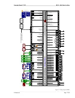
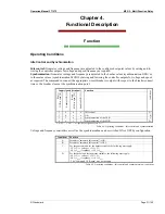
Figure 3-2: Wiring diagram MFR 32


