Wolf CGB-2 Series Скачать руководство пользователя страница 24

24

3064810_201804

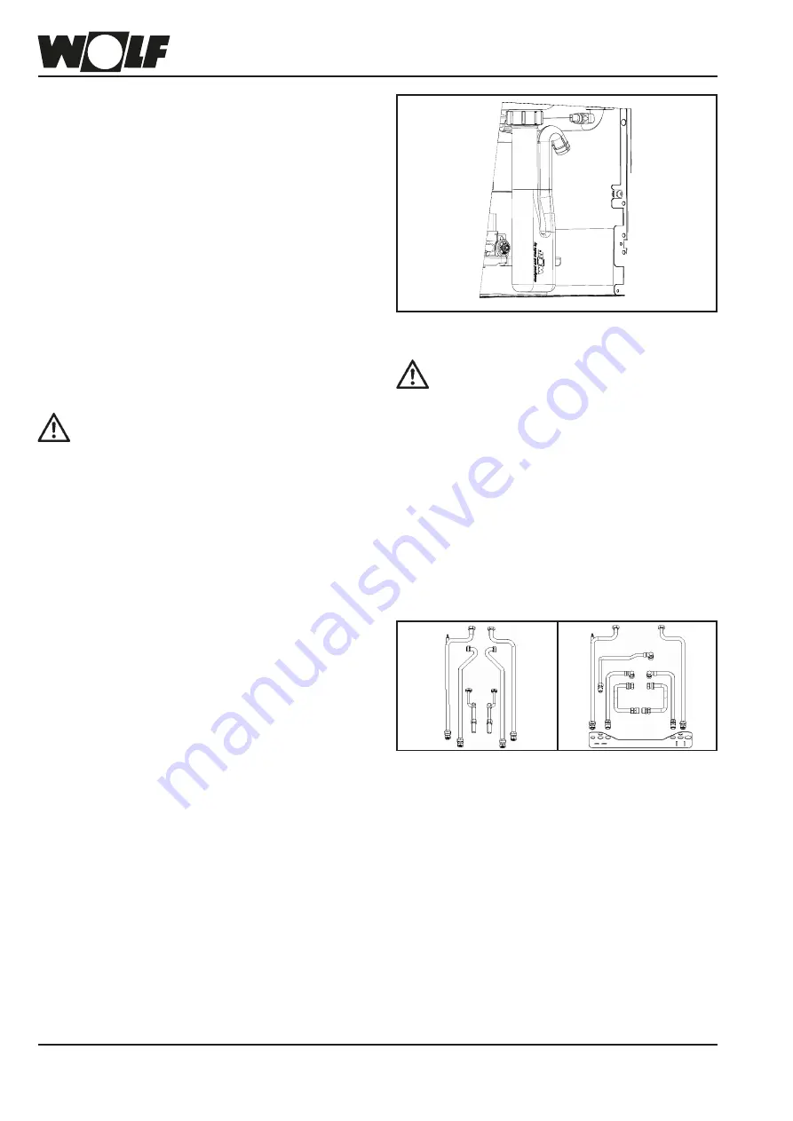
13. Fitting the trap

The trap must be filled with water prior to 

commissioning. Operating the appliance with 

an empty trap presents a risk of poisoning 

or asphyxiation due to flue gases escaping. 

Unscrew the trap, remove and fill until water 

runs out of the drain hole on the side. Refit 

the trap and ensure the gasket seals tightly.

Before  commissioning,  carry  out  a  tightness 

test on all hydraulic pipework:

Test pressure on the DHW side max. 10 bar

Test pressure on the heating water side max. 

4.5 bar

Condensate connection

First, grip the control unit cover on the r.h. side and swivel to the 

side. Then undo the two screws on the r.h. and l.h. sides of the 

front casing. The front casing can then be released upwards.

Fill the supplied trap with water and connect it to the conden-

sate pan connector.

The drain hose must be safely secured above the drain outlet 

(trap).

If the condensate is directly routed to the drain pipe, ventilation 

must be provided so that the drain pipe cannot affect the gas 

condensing boiler.

If installing a neutralising system (accessories), observe the 

instructions supplied.

According to Code of Practice ATV-DVWK- A251 [Germany], 

no neutralising system is required for condensing boilers up 

to 200 kW.

If a neutralising system is used, the national regulations 

regarding the disposal of residues from such systems apply.

Connection to Wolf cylinder

A detailed description is included with the connection set 

(accessories).

Fig: 

Connection set for Wolf cylin-

der CSW-120 

Installation on unfinished walls 

(accessories) 

Fig: 

Connection set for Wolf cylinder 

CSW-120

Installation on finished walls 

(accessories) 

Fig: Trap

Anschluss Wolf - Speicher

Bild 1: Anschlussset für Unterputzinstallation 

Bild 2: Anschlussset für Überputzinstallation 

Содержание CGB-2 Series

Страница 1: ...75174 1600 www WOLF eu Art Nr 3064810_201804 Subject to technical modifications Installation instructions for contractors Wall mounted gas condensing boiler CGB 2 wall mounted gas condensing boiler CGB 2K wall mounted gas condensing combi boiler CGB 2 14 CGB 2 K 20 CGB 2 K 24 ...

Страница 2: ...4 Parameter description 40 Commissioning 25 Filling the heating system trap 52 26 Filling of optional appliance versions 56 27 Draining the heating system 57 28 Determining changing the gas type 58 29 Checking the gas supply pressure 60 30 Adjusting the maximum heating output 61 31 Checking the combustion parameters 62 32 Converting from combi boiler to boiler with cylinder 64 33 Setting the flow ...

Страница 3: ...g system German Immission Control Act Energy Saving Ordinance Germany Inform the system user that these instructions and the other applicable documents must be kept in a safe place Instruct the system user how to operate the heating system 1 4 Applicability of these instructions These installation instructions apply to the CGB 2 K gas condensing boilers 1 5 Acceptance Within 4 weeks of commissioni...

Страница 4: ...w only for combi boiler Standard delivery Accessories The following accessories are required for installing the gas condensing boiler Air flue gas accessories see technical information Control unit for room temperature dependent or weather compensated control AM BM 2 Condensate drain outlet with hose retainer Maintenance shut off valves for heating flow and return Gas ball valve with fire protecti...

Страница 5: ...ocumentation supplied by WOLF Intended use of the boiler includes exclusive use for hot water heating systems in accordance with DIN EN 12828 Never remove bypass or otherwise disable any safety or monitoring equipment Operate the boiler only if it is in perfect technical condition Any faults or damage which impact or might impact upon safety must be remedied immediately by a qualified con tractor ...

Страница 6: ... Isolate the system from the power supply e g by remov ing the separate mains fuse or by means of a main switch or a heating emergency stop switch and check to ensure there is no voltage Safeguard the system against reconnection Inspection and service Ensure the correct operation of the gas boiler by having a contractor carry out inspections at least once a year and maintenance repair when require...

Страница 7: ...live electrical components risk of burning from hot components Fig Gas combination valve Danger from live electrical components Risk of poisoning or explosion in the event of gas escaping Gaskombiventil Fig Gas connection Risk of poisoning or explosion in the event of gas escaping Fig Terminal box Danger from electrical voltage ...

Страница 8: ...4 8 4 100100 70 440 6 5 4 4 0 3 1 7 0 1 6 5 2 6 1 190 7 9 0 378 48 3 Dimensions CGB 2 Wall mounted gas condensing boiler Ø 60 100 Ø 80 125 Cylinder return G Cylinder flow G Heating flow G Heating return G Gas connection R 344 8 4 100100 70 440 6 5 4 4 0 3 1 7 0 1 6 5 2 6 1 190 7 9 0 378 48 ...

Страница 9: ... condensing combi boiler Cold water connection with connection elbow G DHW connection with connection elbow G Heating flow G Heating return G Gas connection R 0303958 8 4 2 6 1 4 0 3 1 1 6 5 6 5 4 70 100 100 440 344 7 7 0 48 378 190 7 9 0 Ø 60 100 Ø 80 125 0000303958 8 4 2 6 1 4 0 3 1 1 6 5 6 5 4 70 100 100 440 344 7 7 0 48 378 190 ...

Страница 10: ...fficiency at 30 partial load and TR 30 C Hi net cv Hs gross cv 109 98 109 98 109 98 109 98 109 98 Flow temperature factory setting C 75 75 75 75 75 Flow temperature up to approx C 90 90 90 90 90 Max overall pressure bar 3 0 3 0 3 0 3 0 3 0 Max residual head for heating circuit HE pump EEI 0 23 600 l h pump rate 14 kW at t 20 K mbar 550 550 550 550 550 860 l h pump rate 20 kW at t 20 K mbar 430 430...

Страница 11: ...at 10 Combustion chamber temperature sensor eHLSC sensor 11 Burner 12 Heating water heat exchanger 13 Flue gas temperature sensor 14 Pressure sensor 15 Return temperature sensor 16 Boiler water temperature sensor 17 Heating circuit pump with air vent valve 22 Heating return 23 Cylinder return 24 Gas supply pipe 25 Cylinder flow 26 Heating flow CGB 2 Wall mounted gas condensing boiler 1 8 9 10 11 1...

Страница 12: ...11 Burner 12 Heating water heat exchanger 13 Flue gas temperature sensor 14 Pressure sensor 15 Return temperature sensor 16 Boiler water temperature sensor 17 Heating circuit pump with air vent valve 18 Plate heat exchanger 19 Flow limiter 20 Flow sensor 21 DHW outlet temperature sensor 22 Heating return 23 Cold water connection 24 Gas supply pipe 25 DHW connection 26 Heating flow CGB 2K Wall moun...

Страница 13: ... value are stored in the system Calibration For all gases the ionisation current is at its maximum when Lambda λ air ratio 1 The system calibrates automatically by briefly shifting to Lambda 1 Briefly increased CO emissions When does the system calibrate 1 Each time the mains supply is switched on 2 Cyclically after a certain number of burner starts and a certain burner runtime 3 After certain fau...

Страница 14: ... side and swivel to the side Then undo the two screws on the r h and l h sides of the front casing The front casing can then be released at the top and removed Fig Front view control unit cover fully open Fig Front view control unit cover slightly partially open Allen screws SW 4 ...

Страница 15: ...gulations must be complied with during installation and operation of the heating system Siting conditions Ventilation and exhaust air facilities and connection to a chimney Electrical connection to the power supply Technical regulations of the gas supply utility company regarding the connection of the gas appliance to the local gas mains Regulations and standards regarding the safety equipment of ...

Страница 16: ...DIN EN 12831 Heating systems in buildings Method for calculation of the de sign heat load DIN EN 12828 Heating systems in buildings Design of water based heating systems DIN EN 13384 Chimneys Thermal and fluid dynamic calculation methods DIN EN 50156 1 VDE 0116 Part 1 Electrical equipment for furnaces VDE 0470 DIN EN 60529 Degrees of protection provided by enclosures IP rating VDI 2035 Prevention ...

Страница 17: ... valve Fig Wolf wall mounted gas condensing boiler CGB 2 wall mounted gas condensing boiler Gas condensing boiler to EN 437 EN 13203 1 EN 15502 1 EN 15502 2 1 EN 60335 1 EN 60335 2 102 EN 62233 EN 61000 3 2 EN 61000 3 3 EN 55014 1 as well as 92 42 EEC Efficiency Directive 2016 426 EU Gas Appliances Directive 2014 30 EU EMC Directive 2014 35 EU Low Voltage Directive 2009 125 EC ErP Directive 2011 6...

Страница 18: ...icals e g fluorine and chlorine or sulphur Such materials are contained in sprays paints adhesives solvents and cleaning agents Under unfavourable conditions these may lead to corrosion including in the flue system During boiler installation ensure that no con taminants e g drilling dust enter the gas boiler as this could lead to appliance faults Please note First determine where the appliance is ...

Страница 19: ...e system component 60 100 Flue system component 80 125 Suspension bracket Installation template Installation panel for unfinished walls Connection panel for surface mounting or DHW Cold water Heating flow Heating return Trap connection Gas connection ...

Страница 20: ...he boiler onto the suspension bracket using the mounting stay Mounting stay Fig Mounting stay on the combi boiler Fig Drill holes for suspension bracket Securing the appliance with the suspension bracket When installing the appliance ensure that the fixings have sufficient load bearing capacity Also take into account the condition of the wall as an escape of gas or water might result in a risk of ...

Страница 21: ...ting gas and safety valve drain are routed on finished walls the surface mounted connection bracket accessory can be used to determine the location of connections Bild Anschlusskonsole für Überputzausführung Zubehör für Gasthermen CGB Bild Anschlusskonsole für Überputzausführung Zubehör für Gaskombithermen CGB K Seite 15 Bild Montageschablone Unterputz Bild Rohbaukonsole Unterputz Zubehör für CGB ...

Страница 22: ...sure reducer Observe the regulations of DIN 1988 Germany as well as those of your local water supply utility when connecting cold water and DHW Your warranty is void if the installation does not comply with the illustration shown Note When selecting the installation material for the system observe engineering standards and take into account possible electrochemical processes Mixed installation Sei...

Страница 23: ...e of unsuitable components or assem blies may lead to gas escaping resulting in a risk of poisoning and explosion Install a gas ball valve with fire protection in the gas supply line upstream of the condensing boiler Otherwise explosions may occur during a fire Size the gas supply line in accordance with DVGW TRGI regulations Germany Mount the gas ball valve in an easily acces sible place Carry ou...

Страница 24: ...it to the conden sate pan connector The drain hose must be safely secured above the drain outlet trap If the condensate is directly routed to the drain pipe ventilation must be provided so that the drain pipe cannot affect the gas condensing boiler If installing a neutralising system accessories observe the instructions supplied According to Code of Practice ATV DVWK A251 Germany no neutralising s...

Страница 25: ...balanced flue systems use only original Wolf parts Prior to installation read the technical information regarding air flue gas routing As regulations in the individual Federal States Germany differ we recommend consulting the relevant authorities and local flue gas inspector prior to installation Please note Inspection and testing intervals The gas condensing boiler is equipped with self cal ibrat...

Страница 26: ... alongside 230 V mains cables Danger from live electrical components Please note Turn off the ON OFF switch before removing the casing Never touch electrical components or contacts when the ON OFF switch is in the ON position There is a risk of electrocution that could result in injury or death The main terminals are live even when the ON OFF switch is in the OFF position During servicing and inst...

Страница 27: ... Control unit component overview Removing the HCM 2 casing cover See chapter Casing Netz N L1 Z1 N L1 A1 N L1 ZHP N L1 L1 LP N SF 1 2 AF E1 eBUS 1 2 a b E2 a b 1 2 1 2 1 2 1 2 1 2 Fig Control unit component overview HCM 2 control unit GBC e Terminals Burner control unit ...

Страница 28: ...r low loss header alternatively 0 10 V switching e g 8 V 80 heating output E1 programmable input e g flue gas damper or room thermo stat A1 programmable output LP cylinder loading pump only for appliances with stratification cylinder ZHP heating circuit pump internal wiring ZHP switching parallel to internal appliance pump Z1 230V output when ON OFF switch is ON Power supply Max 1 5 A 345 VA per o...

Страница 29: ...ce IP rating IPX4D is approved for installation in the immediate vicinity of a bath or shower protected area 1 according to DIN VDE 0100 Measures must be taken to prevent jets of water In rooms with a bathtub or shower the appliance may be connected only via an RCD Installation information electrical connection Isolate the system from the power supply before opening Check that the appliance is iso...

Страница 30: ...ould destroy the component Please note Fig Connection of E1 output Netz N L1 Z1 N L1 A1 N L1 ZHP N L1 L1 LP N SF 1 2 AF E1 eBUS 1 2 a b E2 a b 1 2 1 2 1 2 1 2 1 2 Connecting low voltage devices Connecting input E2 Insert and secure the power cable through the cable gland Connect the connection cable for input E2 to terminals E2 as shown in the wiring diagram Only one external voltage of up to 10 V...

Страница 31: ...ore cable cross section 0 5 mm as the con necting cable between the control unit accessory and the condensing boiler Fig Cylinder sensor connection Netz N L1 Z1 N L1 A1 N L1 ZHP N L1 L1 LP N SF 1 2 AF E1 eBUS 1 2 a b E2 a b 1 2 1 2 1 2 1 2 1 2 Fig Connection of digital Wolf control accessories eBUS interface Netz N L1 Z1 N L1 A1 N L1 ZHP N L1 L1 LP N SF 1 2 AF E1 eBUS 1 2 a b E2 a b 1 2 1 2 1 2 1 ...

Страница 32: ...r emissions test and frost protection gn ge M 230V br bl A1 N L1 L1 LP N SF 1 2 AF E1 eBUS 1 2 a b E2 a b 1 2 1 2 1 2 1 2 1 2 E1 programmable input e g flue gas damper A1 programmable output Flue gas damper ventilation air damper electrical connection Isolate the system from the power supply before opening Check that the appliance is isolated from the power supply Swivel the front panel to one sid...

Страница 33: ...n be programmed and displayed Specification 3 LCD screen 4 quick start keys 1 rotary selector with pushbutton function Please note Use when BM 2 is deployed as a remote control or in a cascade circuit AM is always in the boiler AM BM 2 Operating mode Heating mode Burner status ON Status Insert the AM or BM 2 in the slot above the ON OFF switch Wolf logo Both modules can be plugged into this slot F...

Страница 34: ...34 3064810_201804 18 Removing the display module programming unit Removing the BM 2 programming unit or AM display module ...

Страница 35: ...r Wolf boiler is not equipped with an AM display module ignore this page Further functions and descriptions can be found in the installation instructions for contractors or the user operating instructions for the AM display module Set boiler temperature if BM 2 used as remote control no function Set DHW temperature if BM 2 as remote control no function Enable emissions test mode for flue gas inspe...

Страница 36: ... test End Rem time in min T_boiler T_return Calibration Extend time End Contractor Contractor code 1111 Back Relay test System Parameter Parameter reset Message history Back Displays Back T_boiler in C System pressure in bar T_flue gas C T_outside in C T_return in C T_DHW in C T_DHW outl in C DHW DFL flow rate in l min Input E1 Modulation level in IO set value Wolf service ZHP speed Burner starts ...

Страница 37: ...ay test function has been enabled Cascade Cascade module in system enabled BMS Appliance is controlled by building management system BMS 100 cali Appliance is calibrating the flue gas system External disable External disabling of the heating appliance input E1 closed OWHA Boiler burner status Display shows Meaning OFF No burner demand Pre flush Fan operation before burner start Ignition Gas valves...

Страница 38: ...und in the installation instructions for contractors or the user operating instructions for the BM 2 programming unit Key 1 Key 2 Key 3 Key 4 14 12 20 01 15 1 5 bar 25 2 C 1 x Boiler water tem perature Boiler Heating mode Pressure Status display Screen header Time Date Rotary selector with pushbutton function System data display content varies Quick start keys Operating mode Burner status Burner O...

Страница 39: ...tor eBUS address 1 1 1 1 5 HG12 Gas type Nat gas Nat gas Nat gas Nat gas LPG HG13 Function input E1 Various functions can be assigned to input E1 none none none var var HG14 Function output A1 230 V AC Various functions can be assigned to output A1 none none none var var HG15 Cylinder hysteresis switching differential during cyl reheating C 5 5 5 1 30 HG16 Pump rate HC minimum 45 45 45 15 100 HG17...

Страница 40: ...ppliance output Parameter HG04 Upper burner output HZ Factory setting see table Setting range 1 to 100 Individual setting _____ The burner switching hysteresis regulates the boiler water temperature within the set range by switching the burner on and off The higher the start stop temperature differential is set the greater will be the fluctuation in boiler water temperature around the set value wi...

Страница 41: ...of the burner cycle block The burner cycle block is reset by switching the ON OFF switch OFF and ON or by briefly pressing the reset button Parameter HG09 Burner cycle block Factory setting see table Setting range 1 to 30 min Individual setting _____ If multiple heat generators are controlled in one heating system with a cas cade module addresses must be assigned to each heat generator Each heat g...

Страница 42: ...without burner burner disabled When contact E1 is closed the burner is disabled Heating circuit pump 3 way valve and cylinder primary pump continue running in standard mode The burner is enabled in emissions test mode and in frost protection mode Opening contact E1 enables the burner again Flue gas damper Flue gas ventilation air damper Function monitoring of the flue gas ventilation air damper wi...

Страница 43: ...Flue gas damper Flue gas ventilation air damper Output A1 is activated first before each burner start The burner will however only be enabled after input E1 has been closed Closed contact E1 is a pre requisite for enabling burner in central heating DHW and emissions test mode If output A1 is activated and does not close input E1 within 2 minutes a fault is generated FC 8 If output A1 is deactivate...

Страница 44: ...range 15 to 100 Individual setting _____ In heating mode the internal appliance pump does not regulate below this set value Independent of pump control type set in HG37 Parameter HG16 Pump rate HC minimum Factory setting see table Setting range 15 to 100 Individual setting _____ After completing cylinder heating in summer mode the cylinder has reached the set temperature the cylinder primary pump ...

Страница 45: ...ner switching differential Parameter HG22 Maximum boiler temperature TK max Factory setting see table Setting range 50 to 90 C Individual setting _____ The control unit is equipped with an electronic boiler thermostat which has an adjustable minimum start temperature The burner is switched on subject to the cycle block if this temperature is not achieved when heat is demanded If there is no heat d...

Страница 46: ... number of available eBUS subscribers OFF BUS feed is always switched OFF ON BUS feed is always switched ON Auto The control unit switches the BUS feed ON or OFF automatically Parameter HG34 eBUS feed Factory setting see table Setting range OFF to ON Individual setting _____ For setting the type of pump speed control in heating mode cascade operation and with BMS Constant Fixed pump speed HG17 Lin...

Страница 47: ...nal appliance pump is enabled as a feed pump Thermostatic boiler control set value is specified by mixer circuits Input E2 not assigned MK1 MK2 M M System configuration 11 Plate heat exchanger for system separation Burner is enabled subject to demand from the header temperature control Feed heating circuit pump ZHP enabled as a feed pump for header demand Header temperature control Input E2 Header...

Страница 48: ...approaching TKmax HG22 is enabled Shutdown when TKmax is reached BMS E2 BMS C E2 System configuration 52 BMS set boiler temperature Burner is enabled subject to demand from the boiler thermostat Internal appliance pump is enabled as a feed pump from 2 V Thermostatic boiler control Input E2 0 10 V control from the external controller 0 2 V burner OFF 2 10 V set boiler water temperature TKmin HG21 T...

Страница 49: ...Cali comp ON and Cali active ON appears in HG parameter 43 on the display The IO default value is an operand for the electronic gas air mixture and deter mines the CO2 level By reducing the IO default value HG43 the CO2 value can be lowered over the entire output range The default value should not be increased reduced on newly installed applianc es or in the event of a burner or IO electrode repla...

Страница 50: ... HG45 to 2 5 adjust HG43 IO reduction default value to 5 to achieve the set Lambda CGB 2 14 There is a separate setting table for each model of the CGB 2 HG45 Flue system DN 0 2 5 5 7 5 C33x DN 60 100 0 m 3 5 m 3 5 m 7 m 7 m 10 5 m 10 5 m 14 m C33x DN 80 125 0 m 5 5 m 5 5 m 11 m 11 m 16 5 m 16 5 m 22 m C33x DN 110 160 0 m 6 25 m 6 25 m 12 5 m 12 5 m 18 75 m 18 75 m 25 m Other balanced flue systems...

Страница 51: ...F SF SAF SAF DHW cylinder DHW cylinder LP Low loss header Low loss header Collector The excess temperature differential between the header temperature and the boiler water temperature during header heating is selected with parameter HG46 The boiler water temperature continues to be limited by the maximum boiler water temperature parameter HG22 Parameter HG46 Excess boiler temperature header Factor...

Страница 52: ...heating water heat exchanger the pH value of the heating water must be between 6 5 and 9 0 In mixed installations a pH value of 8 2 to 9 0 must be maintained in accordance with VDI 2035 The pH value should be checked again 8 12 weeks after commissioning as under certain circumstances chemical reactions may cause it to change If it does not fall within this range after 8 12 weeks remedial measures ...

Страница 53: ...kW the fill and top up water must be in the range of 2 to 11 2 dH If the total hardness of the untreated potable water is too high some of the filling and top up water must be desalinated A desalinated water must be added A 100 Cmax 0 1 dH Cpotable water 0 1 dH x 100 Cmax Maximum permissible total hardness in dH Cpotable water Total hardness of untreated potable water in dH A 100 11 2 dH 0 1 dH 18...

Страница 54: ... The gas condensing boiler must be switched OFF Close the gas ball valve Open the cap of the automatic air vent valve on the high efficiency pump by one revolution Open all radiator valves Open the flow and return valves on the boiler Slowly fill the entire heating system and appliance in a cold condition to approx 2 bar via the return Never use inhibitors or antifreeze Bleed all radiators with a ...

Страница 55: ...r at the red ON OFF switch in the WOLF logo Note The condensate hose attached to the trap must not form a loop or roll up as this could lead to impaired operation Trap Fig Trap 25 Filling the heating system trap When installing an automatic vent lock the lower threaded connection of the rotary joint underneath the combustion chamber floor Check the system pressure again and top up with water if re...

Страница 56: ...g to DIN EN 1717 hydraulic separators of type CA are approved for liquids up to and including hazard category 3 e g heating water without inhibitors For Germany and Austria only drinking water may be used for the initial filling of the heating system using the filling facility An initial filling with treated water deionised water etc corresponds to a higher hazard category for which the CA hydraul...

Страница 57: ...tch in the WOLF logo Close the gas ball valve Allow the temperature in the heating circuit to cool to at least 40 C Risk of scalding Safeguard the heating system against accidental reconnection to the power supply Open the drain valve boiler drain fill valve on site Open the air vent valves on the radiators Drain the heating water ...

Страница 58: ...d supply pressures Country Appliance category Supply pressure in mbar Natural gas LPG Natural gas LPG Nom Min Max Nom Min Max DE II2N3P 20 18 25 50 42 5 57 5 AT II2H3P 20 18 25 50 42 5 57 5 BE I2N I3B P 20 25 18 30 30 25 35 ES IE II2N3 20 18 25 28 30 25 35 37 25 45 FR II2N3B P 20 25 18 30 30 25 35 FR II2N3B P 20 25 18 30 50 42 5 57 5 BA BY II2N3P 20 18 25 37 25 45 DK EE FI GB GR HR IT LT NO PT RO ...

Страница 59: ...tly set 2 Set adjusting screw A on the gas valve to 2 3 Press the red ON OFF switch to switch ON the boiler 4 Set the gas type at the contractor level Press the operating button Þ Main menu Select the contractor level by rotating and pressing the operating button Enter code 1111 and confirm Select HG parameter HG12 and set to LPG Exit the contractor level Update the type plate Affix the label Conv...

Страница 60: ...of the gas combination valve with a screwdriver Do not remove the screw 3 Connect the pressure gauge 4 Open the gas ball valve 5 Switch the gas condensing boiler ON 6 After the boiler has started read the supply pressure on the pressure gauge and enter it in the commissioning report 7 Turn OFF the boiler close the gas ball valve remove the pressure gauge and tighten the screw in the pressure test ...

Страница 61: ...ting the maximum heating output relative to a flow return temperature of 80 60 C Display value Heating output kW Table Output settings 24 kW appliance Display value 21 30 40 50 60 70 80 90 100 Heating output kW 4 8 7 3 10 2 13 0 15 8 18 6 21 5 24 3 27 1 20 kW appliance Display value 23 30 40 50 60 70 80 90 100 Heating output kW 3 8 5 5 7 9 10 3 12 6 15 0 17 4 19 8 22 2 14 kW appliance Display valu...

Страница 62: ...nd close the test port Ensure the screws are tightly secured Checking the flue gas parameters When the test port is open flue gas can escape into the installation room There is a risk of as phyxiation 1 Remove screw B from the right hand test port 2 Open the gas ball valve 3 Insert the test probe 4 Switch ON the boiler and select Emissions test via the function keys 5 Carry out the checks after a ...

Страница 63: ...ter description 4 If the CO2 or O2 value remains outside the respective range the flue gas values can be adjusted via parameter HG43 Check the electrodes for wear and contamination Clean the electrodes with a small brush not with a wire brush or sandpaper Check the electrode gaps If the gaps do not correspond to the drawing or the electrodes are damaged replace the elec trodes and gaskets and alig...

Страница 64: ... water return block Then secure the connections to the panel using the two circlips Attach them to the free connections on the panel Connect the cylinder sensor to the terminal strip on the control unit Refit the filled trap Open fill the heating water DHW and cold water lines 2 Boiler with cylinder to combi boiler Disconnect the system from the power supply The gas condensing boiler must be switc...

Страница 65: ...etween 5 and 13 l min Procedure Manually pull out the green rotary selector forwards Increase flow rate Þ rotate counter clockwise in direction Reduce flow rate Þ rotate clockwise in direction Check the selected flow rate on the display of the AM display module or the BM 2 programming unit Manually push in the green rotary selector to lock it Recommended draw off rate Appliance type ΔT 40 K ΔT 50 ...

Страница 66: ...tilise the condensing effect as fully as possible while minimising the electrical energy required by the pump This is achieved by constantly maintaining a prescribed spread 3 Fixed speed setting constant The heating circuit pump runs at the fixed set speed both for minimum and maximum burner output The pump rate is not controlled in relation to the required heating load and power consumption is no...

Страница 67: ...not warm up properly Carry out hydraulic balancing i e reduce the flow rate of hotter radiators Increase the pump speed HG16 In the spring and autumn the required room temperature is not achieved Increase the set room temperature at the controller e g with set value setting 4 The required room temperature is not achieved when outside temperatures are very low Select a steeper heating curve at the ...

Страница 68: ...stem filled and water treatment carried out in line with Technical information water treatment pH value set Total hardness set _______________ pH value _______________ dH 4 Appliance and system vented 5 System pressure 2 0 2 5 bar 6 Water connections checked for tightness 7 Trap filled 8 Gas valve set to gas type Natural gas LPG Wobbe index _________________ kWh m Calorific value heating _________...

Страница 69: ...g to Flue length compensation table in contractor parameter HG45 17 Gas type and heating output entered on label 18 Balanced flue system checked 19 Flue gas emissions test emissions test mode Gross flue gas temperature Intake air temperature Net flue gas temperature Carbon dioxide content CO2 or oxygen content O2 Carbon monoxide content CO _____________ tA C _____________ tA C _____________ tA tL ...

Страница 70: ... temperature 85 C factory setting Exceeding this temperature causes the boiler to shut down and results in a burner cycle block factory setting 7 min Flue gas temperature sensor The flue gas temperature sensor shuts down the boiler when the flue gas temperature exceeds 110 C This results in a lockout fault Þ Fault code 07 The flue gas temperature is determined by a sensor in the condensate pan Com...

Страница 71: ...The maximum safe differential pressure at start Δpmax saf start 25 d The maximum functional differential pressure at the highest thermal load Δpmax func max 25 e The minimum safe differential pressure Δpmin saf 200 Balanced flue system Provide ventilation for B23 B33 C53 B23 B33 C13x C53 C83x C53x C33x IIIIIIIIIIIIIIIIIIIIIIIIIIIIIIIIIIIIIIIIIIIIIIIIIIIIIIIIIIIIIIIIIIIIIIIIIIIIIIIIIIIIIIIIIIIIIIII...

Страница 72: ...oncentric connection to a moisture resistant chimney and combustion air through an external wall room sealed Calculation to EN 13384 room sealed balanced flue manufacturer C93x Flue for installation in a duct Connecting pipe DN60 100 vertical DN60 rigid flexible 17 13 17 13 17 13 C93x Flue for installation in a duct Connecting pipe DN60 100 or DN80 125 vertical DN80 rigid flexible 18 14 21 17 26 2...

Страница 73: ...ooms whose ceiling also forms the roof or where only the roof construction is located above the ceiling If the balanced flue passes through different floors of the building route the pipes outside the boiler room inside a duct with at least 90 min fire resistance In low rise residential buildings building category 1 to 2 a minimum of 30 min fire resistance is re quired Fire may spread if these ins...

Страница 74: ... pipe length and the length of any pipe bends Example for a 60 100 system1 Straight balanced flue pipe length 1 5 m L straight length bend length 1 x 87 bend 1 5 m L 1 5 m 1 x 1 5 m 2 x 1 3 m 2 x 45 bends 2 x 1 3 m L 5 6 m Calculating the balanced flue length Note To avoid reciprocal interference between air and flue gas pipes routed above the roof we recommend maintaining a minimum clearance of 2...

Страница 75: ...ated and must be approved for condensing operation If necessary obtain the connection piece from the chimney manufacturer The air apertures to the boiler room must be completely free from obstruction Connection to a moisture resistant flue type B23 for open flue operation For this option observe the regulations concerning ventilation for boiler rooms acc to DVGW TRGI Connection to a moisture resis...

Страница 76: ...liance press quick start key 3 to activate the Emissions test è CGB 2 starts Operate the first CGB 2 for at least 5 minutes Check the CO2 content in the air connectors on all other appliances If the CO2 value exceeds 0 2 within 15 minutes the leak must be found and remedied Subsequently close all test ports again When doing so ensure the caps are seated firmly Testing the first CGB 2 for tightness...

Страница 77: ...or DN60 100 slide coupling if required 4 Balanced flue pipe DN60 100 500 mm 1000 mm 2000 mm 5 Balanced flue vertical DN60 100 roof outlet for flat or pitched roofs L 1200 mm L 1200 mm 1700 mm 6 Universal tile for pitched roof 25 45 7 Flat roof collar 8 Bend 45 DN60 100 9 Inspection bend DN60 100 10 Bend 87 DN60 100 11 Pipe collar 12 Support rail 13 Support bend 87 DN60 to DN80 14 Spacer 15 Flue pi...

Страница 78: ...Inspection bend 10 Bend 87 DN60 100 11 Pipe collar 12 Support rail 13 Support bend 87 DN60 to DN80 14 Spacer 15 PP flue pipe DN80 500 mm 1000 mm 2000 mm 16 Duct cover with UV resistant ter minal 17 Spacer bracket 18 Balanced flue horizontal with wind protector 19 Connection to flue gas chimney B33 Length 250 mm with air apertures 17 18 18 11 11 11 11 19 4 160 160 4 0 0 2 10 4 4 17 17 9 9 12 13 14 ...

Страница 79: ...10 C Installation example for bal anced flue duct C33x Install horizontal pipe with 3 slope towards boiler Please note 1 Gas condensing boiler 3 Separator slide coupling if required 4 Balanced flue DN60 100 500 mm 1000 mm 2000 mm 9 Inspection bend 11 Pipe collar 12 Support rail 13 Support bend 87 DN60 100 14 Spacer 16 Duct cover with UV resistant terminal 17 Spacer bracket ...

Страница 80: ...0 mm 45 min 73 mm Flat roof Affix ceiling outlet 7 approx Ø 130 mm to the roof cover Pitched roof For 6 observe the installation instructions on the cowl regarding roof pitches If an inspection aperture is required for the balanced flue insert a balanced flue pipe with inspection aperture 2 200 mm length Insert roof outlet 5 into the roof from above and secure vertically with the mounting bracket ...

Страница 81: ...or pitched roofs L 1200 mm L 1800 mm 8 Separator slide coupling if required 9 Bend 45 DN 80 125 10 Inspection bend 87 DN 80 125 11 Bend 87 DN 80 125 12 Universal tile for pitched roof 25 45 13 Klöber adaptor 20 50 14 Flat roof collar Notes When installing slide the separator 8 fully into the female connec tion Push the next balanced flue pipe 4 50 mm dim S into the female connection of the separat...

Страница 82: ...ith wind protector 16 Pipe collar 17 External wall panel 87 DN80 125 with smooth air pipe end 18 Balanced flue pipe external walls DN80 125 19 Air inlet external wall DN80 125 20 Conc outlet terminal with clamp fitting 21 Connection to a flue gas chimney B33 Length 250 mm with air aperture 22 Support rail 23 Support bend 87 DN80 24 Spacer 25 PP flue pipe DN80 26 Duct cover with UV resistant termin...

Страница 83: ... balanced flue system DN80 185 horizontal and DN80 vertical Connection to a concentric balanced flue inside a duct examples DN80 125 C33x Connection to a flue inside a duct C93x 1 Gas condensing boiler 2 Adaptor DN60 100 to DN80 125 4 Balanced flue pipe DN80 125 500 mm 1000 mm 2000 mm 5 Spacer bracket 8 Separator slide coupling if required 10 Inspection bend 87 DN 80 125 11 Support bend 87 DN80 12...

Страница 84: ...00 mm Install eccentric balanced flue distributor 80 80 mm 31 for separate air supply flue gas routing downstream of connection adaptor DN80 125 2 with a test connector When connecting a balanced flue certified acc to Building Regulations observe the permit of the relevant body Install the horizontal flue pipe with a slope of approx 3 6 cm m towards the boiler Route the horizontal air supply with ...

Страница 85: ...0 mm to the roof cover Pitched roof For 12 observe the installation instructions on the cowl regarding roof pitches If an inspection aperture is required for the balanced flue insert a balanced flue with inspection aperture 3 200 mm length Insert roof outlet 7 into the roof from above and secure vertically with 6 to a rafter or brickwork Install the roof outlet only in its original condition Modif...

Страница 86: ...derfloor heating is connected parameters HG16 and HG17 Recommendation HG16 Þ 75 and HG17 Þ 100 When connecting an underfloor heating system with an output demand in excess of approx 10 kW a 3 way mixer accesso ries MM and an additional pump are required Install a regulating valve in the return this can be used to reduce the excessive head of the additional pump if required Ensure the system user c...

Страница 87: ...r Contractor Back Contractor Contractor code 1111 Back Relay test System Parameter Parameter reset Message history Back No Yes Reset parameters to factory settings No Yes Reset parameters to factory settings Parameter Reset A parameter reset returns all parameters to their factory settings See Parameter settings Password Authorisation required ...

Страница 88: ...18 091 32 3701 66 1005 100 339 1 17 183 33 3549 67 971 101 330 0 16 325 34 3403 68 938 102 320 1 15 515 35 3265 69 906 103 311 2 14 750 36 3133 70 876 104 302 3 14 027 37 3007 71 846 105 294 4 13 344 38 2887 72 818 106 285 5 12 697 39 2772 73 791 107 277 6 12 086 40 2662 74 765 108 270 7 11 508 41 2558 75 740 109 262 8 10 961 42 2458 76 716 110 255 9 10 442 43 2362 77 693 111 248 10 9952 44 2271 7...

Страница 89: ... acknowledged and do not lead directly to the appliance being switched off However the causes of the warnings can lead to malfunctions of the appliance system or to faults and should therefore be rectified by a qualified contractor Please note Faults must only be rectified by qualified personnel Component or system damage can result if a lockout fault message is acknowledged several times without ...

Страница 90: ... check cables and plugs If electrical connection OK and no func tion Replace the pump Press reset button 03 dt flow drift Temperature differential between temperature sensors eHLSC1 and eHLSC2 6 C at the combustion chamber eHLSC Faulty replace eHLSC Press reset button 04 No flame established When the burner starts no flame forms by the end of safety time Monitoring electrode faulty Ignition electr...

Страница 91: ...ction OK and no func tion Replace pump Press reset button 07 Flue gas TL excess temperature The flue gas temperature has exceeded the flue gas temperature limiter s shutdown temperature of 110 C Combustion chamber module Combustion chamber Flue gas temperature limiter Combustion chamber module Check installation position Combustion chamber If the combustion chamber is heavily contaminated carry ou...

Страница 92: ...ure sensor eBus Outside temperature sensor See instructions for eBUS outside sensor Wireless outside sensor See instructions for wireless outside sen sor Press reset button 16 Return sensor faulty Return sensor or sensor lead has short circuit or break Return sensor 100 C Return sensor Check leads and plug in connections If OK and no function replace the return sensor Press reset button 20 GCV rel...

Страница 93: ...e correct boiler coding card Press reset button and enter contractor code 1111 38 BCC update required Boiler coding card fault PCB requires a new boiler coding card replacement Reinsert boiler coding card Replace boiler coding card Press reset button 39 BCC system error Faulty boiler coding card BCC copy process not started Use ON OFF switch Replace boiler coding card Press reset button and enter ...

Страница 94: ...y Press reset button Set HG43 IO default value and HG44 KL offset to factory setting must be done by contractor 54 GLV actuators Flue gas recirculation Incorrect gas type setting Incorrect gas restrictor Gas valve faulty Fan faulty Flue gas recirculation Check the flue path inside and outside the appliance leaking blocked Check wind effect Gas type setting Check gas type setting on the gas valve a...

Страница 95: ...de Check electrical wiring and connections Check the condition of the electrode clean or replace if necessary Adjust gap and position or replace if neces sary Carry out 100 calibration Replace boiler coding card Check the electrical connection of the HCM 2 low voltage side 58 Timeout calibration The heating appliance cannot carry out calibration Flue gas recirculation Fan faulty Inadequate heat tr...

Страница 96: ...cessary Adjust gap and position or replace if neces sary Check the electrical connection of the HCM 2 low voltage side 99 Burner control unit system fault Loose contact PWM connector or fan power connection Internal burner control unit fault GBC e PCB faulty Unknown GBC e PCB Check plug lead for PWM signal fan for any loose contact Internal burner control unit fault Reset only possible after power...

Страница 97: ...ation time Flame failure after safety time Flame failure during operation Check replace monitoring electrode flue gas path blocked Condensate drain blocked Check the gas supply pressure 24 Speed below or above limit Fan speed does not reach set speed or standstill Check flue system PWM and power cable to fan Check connection between CGBe and HCM 2 43 Many burner starts Excessive number of burner s...

Страница 98: ...heck of GBC e failed System error Check for a strong electromagnetic field nearby Switch power ON OFF reset if necessary Press reset button 58 Timeout calibration The heating appliance cannot carry out calibration Flue gas recirculation Fan faulty Inadequate heat transfer Flue gas recirculation Check the flue path inside and outside the appliance leaking blocked Fan Check that the fan and its wiri...

Страница 99: ...N L1 HCM 2 E2 a b X10 1 X8 8 1 X7 13 1 sw rt vi 6 X6 1 X4 1 5 X5 1 X3 1 2 4 1 1 2 9 10 2 eBus X32 X30 8 1 X34 X33 rt sw vi br bl gr gn ge S1 sw br or rt WLAN LAN S1 rt or br sw X31 6 1 X1 1 4 23V 3V3 eBus GND wBus 5V X11 1 9 GND 3V3 eBus N C wBus VISTX CCTX CCRX X1 1 16 X2 1 10 VISRX WOLF sw ws rt X1 GBC E sw rt bl br gegn ws sw rt bl gn br gn br bl br bl PWM PE WW N HZ gn ge bn ws gn ge bn ws sw ...

Страница 100: ...ignal GND GND GND V2 Mod V1 23V V1 23V Ion Zünd L Vent L Vent N Zünd N 230V L 230V N FE 23V CC RX CC TX GND Res V2 Mod Vent GND Vent Hall Vent PWM Abgas eSTB1 eSTB2 STB1A STB1A STB1 STB1 5 4 3 2 1 bl br 3 4 5 2 1 bl bl sw br bl br gr sw br vi ge sw bn vi rt br sw bl ge rt gn bn gn ws bl gr rt gn X6 HCM 2 17 X3 1 X2 X1 GBC e 1 8 X4 5 1 sw sw gnge gn br ws sw br bl rt mA gnge bn bl sw ws gnge gnge 3...

Страница 101: ...output Prated kW 14 19 24 Seasonal space heating energy efficiency ηs 93 93 93 Annual energy consumption for space heating QHE kWh 7570 10581 13290 Sound power level indoors LWA dB 47 47 48 Any specific precautions that shall be taken when the space heater is assembled installed or maintained See installation instruction See installation instruction See installation instruction Wolf GmbH Postfach ...

Страница 102: ...ted kW 19 24 Annual energy consumption for space heating QHE kWh 10568 13308 Annual fuel consumption for water heating AFC GJ 17 17 Seasonal space heating energy efficiency ηs 93 93 Seasonal water heating energy efficiency ηwh 85 85 Sound power level indoors LWA dB 47 48 Any specific precautions that shall be taken when the space heater is assembled installed or maintained See installation instruc...

Страница 103: ...012 Auxiliary electricity consumption in standby mode PSB kW 0 003 0 003 0 003 0 003 0 003 Seasonal space heating energy efficiency ns 93 93 93 93 93 Useful efficiency at rated heat output and high temperature regime n4 88 1 87 8 87 8 87 8 87 8 Useful efficiency at 30 of rated heat output and low tem perature regime n1 98 0 97 7 97 7 97 7 97 7 Standby heat loss Pstby kW 0 033 0 033 0 033 0 032 0 0...

Страница 104: ...104 3064810_201804 46 Notes ...

Страница 105: ...3064810_201804 105 46 Notes ...

Страница 106: ...106 3064810_201804 46 Notes ...

Страница 107: ...02 1 A1 2015 DIN EN 60335 1 2012 AC 2014 EN 60335 1 2012 AC 2014 DIN EN 60335 2 102 2010 EN 60335 1 2006 A1 2010 DIN EN 62233 2009 EN 62233 2008 DIN EN 61000 3 2 2010 EN 61000 3 2 2006 A1 2009 A2 2009 DIN EN 61000 3 3 2010 EN 61000 3 3 2008 DIN EN 55014 1 2012 EN 55014 1 2006 A1 2009 A2 2011 In accordance with the following Directives 92 42 EEC Efficiency Directive 2016 426 EU Gas Appliances Direc...

Страница 108: ...WOLF GMBH POSTFACH 1380 D 84048 MAINBURG TEL 49 0 87 51 74 0 FAX 49 0 87 51 74 16 00 www WOLF eu Document no 3064810_201804 Subject to technical modifications ...

Отзывы: