


ENGLISH
14
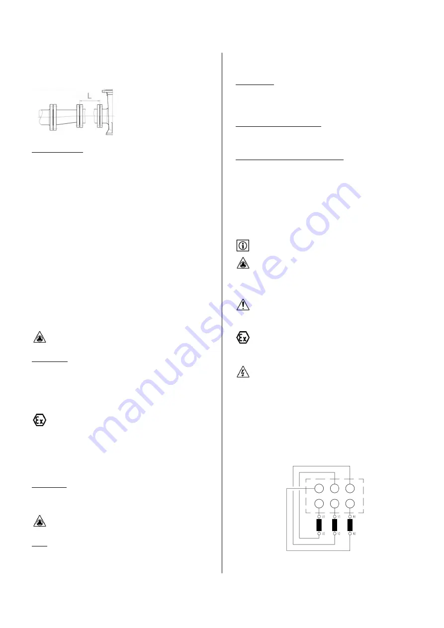
eccentric transition part. It is recommended to install a straight pipe
before the pump inlet (size L should be 2 to 3 times the pipe nominal
dimension). The suction line should be laid with a downward slope
toward the pump.
Suction lift operation :
Nominal diameter of the suction pipe must be equal or a size larger than
the pump suction flange diameter. Pipe inlet should be set below lower
liquid level. Install a strainer with foot valve to prevent priming loss. The
strainer will be installed far enough from the pit bottom to avoid
excessive suction head losses and particles intake. Ensure there is no air
intake along the suction pipe and that the suction pipe is inclined
upwards towards the pump inlet. Avoid air pocket creation.
Suction line should be airtight and as short as possible. Use of large
radius bends should be preferred. If possible the nominal diameter of
suction pipe will be the same as pump nominal diameter. The size of
pipe will be selected to limit flow speed to 2m/s. A straight pipe (length
= 2 times the pipe diameter) will be installed on pump suction side.
During pump priming period air contained in the suction pipe is
eliminated and liquid is lifted up to suction flange level.
When suction pipe is full of liquid the pump is acting like a standard
centrifugal pump.
Priming time will increase if a larger pipe diameter is used or if pipe
length is increased. Any air intake along this pipe will delay or avoid
pump priming.
Check that pump required NPSH (NPSH
R
) is lower than system
available NPSH (NPSH
A
).
Discharge pipe :
During priming time, air contained in suction pipe is pumped through
the pump to the discharge pipe. Free exhaust of this gas to the
atmosphere should be possible.
If this requirement cannot be met, a vent pipe connected before the
NRV and going back to the pit/sump or an automatic air-vent valve
should be installed.
If an explosion hazard exists, check that the area around the outlet
of this venting pipe is identified as an ATEX zone.
A vent pipe or an automatic air vent valve must be installed ahead of
the non-return valve. A motorized valve can be used to close vent pipe
and avoid recirculation of fluid during normal operation.
Nominal diameter of discharge pipe should be chosen to ensure a max
flow speed of 3m/s.
Filter/strainer :
If required a filter can be installed before the pump intake. To ensure
proper working of pump the equivalent exchange surface of the strainer
should be 3 time the pipe sectional area.
Clogging state of filter/strainer should be checked regularly.
Valves :
It is advised to install isolating valves on suction and discharge side for
maintenance purpose. Those valves should be of large passage type and
could be locked in position.
Isolating valve on suction side will not be connected directly to pump
suction flange.
Auxiliary piping :
For most of applications a single mechanical seal is used. If the sealing
must be equipped with auxiliary equipments, check that there are no
leakages and that direction of flow is respected.
Single mechanical seal with quench :
External piping system or raised tank should be installed in the state of
the art. Pressure in the quench should not exceed 0,35 bar.
Single mechanical seal with external flushing :
Flushing fluid should be pressurized at 0,5 / 1 bar above pump discharge
pressure.
After pipe work is done turn the pump shaft by hand and check that it
turns freely. If it appears that it is difficult to turn the pump shaft, then
check forces applied by piping to pump casing. Installation of piping
should be done again.
7.3
ELECTRICAL CONNECTION / EARTHING
Check that motor winding corresponds to site electric power
supply characteristics before electrical connections are performed.
Connecting a 230/400V motor on a 400V power supply or
connection of a 400/690V motor on a 690V power supply might
drive to motor destruction if terminal strip are positioned in a wrong
way.
Electrical connection should be performed by qualified personnel
only having necessary agreements and in compliance with local,
national and international regulations.
Equipments used in an ATEX zone will be connected in compliance
with CEI60079-14. It is the responsibility of the end user to select
proper type and size of electric cable.
Respect motor manufacturer instructions to make electric motor
connection (refer to the instructions supplied with the motor. they
are usually indicated inside motor junction box). Sensors will be
connected in compliance with the instructions given in dedicated
instruction manual.
7.3.1
TERMINAL STRIP POSIT IONNING FOR STAR
(Y) AND DELTA (
) CONNECTION (MULTI-
VOLTAGES ELECTRIC MOTORS)
Multi-voltage winding for voltages 230/400V and 400/690V :
6 wiring terminals :
To change motor direction of rotation reverse two phases on wiring
terminals. Connection of earthing terminal is mandatory.
Содержание Wilo-Drain SP
Страница 2: ......
Страница 3: ...FR Notice de montage et de mise en service Wilo Drain SP 4186313 Ed 02 2013 10 Wilo...
Страница 4: ...FRAN AIS 2...
Страница 25: ......
Страница 26: ...24...
Страница 27: ...EN Installation and operating instructions Wilo Drain SP 4186313 Ed 02 2013 10 Wilo...
Страница 28: ...ENGLISH 2...
Страница 49: ...ENGLISH 23...
Страница 50: ......
Страница 51: ......


