46
WhitakerAudio
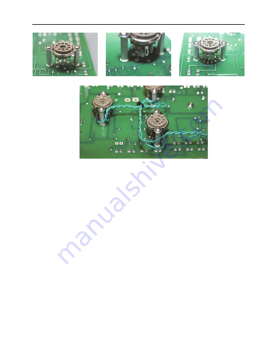
– Install connecting wires from the PWB pads to the tube socket pins. Solder in place.
Materials for these steps can be found in the “Tube Socket Hookup” package. Note that
the heater connections are made separately. The recommended procedure for installing the
connecting wires is as follows:
1) Feed a bare wire from the component side through the pad and into the socket
soldering tab.
2) Crimp in place (see Figure 5.2
b
).
3) From the component side, pull the wire tight and solder in place.
4) Trim the excess lead length.
5) Solder the socket tab.
Table 5.1 shows the pins that should be connected to the PWB.
(
a
)
(
b
)
(
c
)
(
d
)
Figure 5.2
Installation of sockets on the PWB: (
a
) mount the socket on the standoffs, (
b
) insert
connecting wires from the PWB to the socket, (
c
) board-to-socket connections completed, (
d
)
finished job with heater wires installed.
Содержание AM/FM Stereo Tuner 2012
Страница 1: ...WhitakerAudio AM FM StereoTuner User and Assembly Manual...
Страница 11: ...11 AM FM Stereo Tuner Figure 1 1 Schematic diagram of the AM tuner section...
Страница 17: ...17 AM FM Stereo Tuner Figure 1 2 Schematic diagram of the FM tuner section...
Страница 34: ...34 WhitakerAudio Figure 3 1 Component layout for the AM tuner PWB...
Страница 36: ...36 WhitakerAudio Figure 3 3 Component layout for the FM tuner PWB...
Страница 69: ...69 AM FM Stereo Tuner Set the FM tuner board aside it will be used later b...
Страница 101: ...101 AM FM Stereo Tuner Figure 5 11 Chassis view of the AM FM Stereo Tuner...
Страница 159: ...159 AM FM Stereo Tuner...
Страница 160: ...WhitakerAudio AM FM StereoTuner...


