


5-100 Maintenance Procedures
Tubing schematic — LockSpray system
Tubing dimensions – LockSpray system
Port number
Connection
ID (in.)
OD (in.)
Color
Length
(mm)
1
Vial A
0.020
1/16
Orange
680
2
Vial B
0.020
1/16
Orange
680
3
Vial C
0.020
1/16
Orange
680
4
Flow sensor
0.005
1/32
Red
200
5
Waste reservoir
0.040
1/16
Natural
1000
6
Wash reservoir
0.020
1/16
Orange
1000
7
LockSpray selector
pump
0.010
1/16
Blue
300
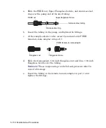
-
Flow sensor to
grounded union
0.005
1/32
Red
60
-
Grounded union to
reference probe
Probe and flow-rate dependent.
A
B
C
3
1
6
5
7
4
2
From pump
From wash bottle
To
reference
probe
Waste
port
From external
reference bottle
(optional)
Flow sensor
Grounded union
Tubing
guides
Lock-spray selector valve
Содержание SYNAPT G2
Страница 18: ...xviii Table of Contents...
Страница 46: ...2 8 Starting Up and Shutting Down the Mass Spectrometer...
Страница 66: ...3 20 Configuring the LockSpray Source...
Страница 228: ...B 24 External Connections 7 Click Next Result The software installs 8 Click Finish...
Страница 232: ...C 4 Materials of construction and compliant solvents...


