background image

June 28, 2016, 715003956 Rev. C

Page 64

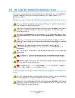
A.7.2

Handling symbols

The following handling symbols and their associated statements can appear on labels affixed to 
the packaging in which instruments, devices, and component parts are shipped. 

Frame, or chassis, terminal

Fuse
Functional ground

Input

Output

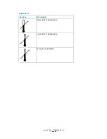
Table A–2:

Symbol

Description

Keep upright!

Keep dry!

Fragile!

Use no hooks!

Table A–1:

Symbol

Description

Содержание ACQUITY QDa

Страница 1: ...ACQUITY QDa Detector Overview and Maintenance Guide 715003956 Revision C Copyright Waters Corporation 2016 All rights reserved ...

Страница 2: ...June 28 2016 715003956 Rev C Page ii ...

Страница 3: ...cument consult the Waters Web site waters com Trademarks ACQUITY Alliance Connections INSIGHT QDa THE SCIENCE OF WHAT S POSSIBLE Waters and Waters Quality Parts are registered trademarks of Waters Corporation RADAR is a trademark of Waters Corporation PEEK is a registered trademark of Victrex PCL Tygon is a registered trademark of Saint Gobain Corporation Viton is a registered trademark of Dupont ...

Страница 4: ...follow Good Laboratory Practice and consult your organization s standard operating procedures Safety hazard symbol notice Documentation needs to be consulted in all cases where the symbol is used to find out the nature of the potential hazard and any actions which have to be taken Table 1 1 Waters contact information Contacting medium Information Internet The Waters Web site includes contact infor...

Страница 5: ...o avoid leaks of materials that are biohazardous or toxins follow these guidelines To confirm the integrity of the source exhaust system renew the source O rings at intervals not exceeding one year To avoid chemical degradation of the source O rings which can withstand exposure only to certain solvents see Appendix C determine whether any solvents you use that are not listed are chemically compati...

Страница 6: ...le Warning To avoid electric shock do not remove the mass spectrometer s protective panels The components they cover are not user serviceable To avoid nonlethal electric shock when the instrument is switched on avoid touching the areas marked with the high voltage warning symbol To touch those areas first switch the instrument off Warning To avoid personal contamination with biohazards toxic mater...

Страница 7: ...s notice Changes or modifications not expressly approved by the party responsible for compliance could void the users authority to operate the equipment This device complies with Part 15 of the FCC Rules Operation is subject to the following two conditions 1 this device may not cause harmful interference and 2 this device must accept any interference received including interference that may cause ...

Страница 8: ...cable European Community directives or Australia EMC compliant Confirms that a manufactured product complies with all applicable United States and Canadian safety requirements Consult instructions for use Alternating current Electrical and electronic equipment with this symbol may contain hazardous substances and should not be disposed of as general waste For compliance with the Waste Electrical a...

Страница 9: ... location of the QC samples in the trays Ensure that QC sample results fall within an acceptable range and evaluate precision from day to day and run to run Data collected when QC samples are out of range might not be valid Do not report these data until you are certain that the instrument performs satisfactorily EMC considerations Canada spectrum management emissions notice This class A digital p...

Страница 10: ...equipment s proper operation This equipment complies with the emission and immunity requirements described in the relevant parts of IEC EN 61326 Electrical equipment for measurement control and laboratory use EMC requirements EC authorized representative Waters Corporation Stamford Avenue Altrincham Road Wilmslow SK9 4AX United Kingdom Telephone 44 161 946 2400 Fax 44 161 946 2480 Contact Quality ...

Страница 11: ...ctor v FCC radiation emissions notice vii Electrical power safety notice vii Equipment misuse notice vii Safety advisories vii Operating this instrument viii Applicable symbols viii Audience and purpose ix Intended use of the ACQUITY QDa Detector ix Calibrating ix Quality control ix EMC considerations ix Canada spectrum management emissions notice ix ISM Classifickation ISM Group 1 Class A ix EC a...

Страница 12: ...Troubleshooting with Connections INSIGHT 26 3 5 Safety and handling 27 3 6 Removing and refitting the source enclosure 28 3 6 1 Removing the source enclosure from the instrument 28 3 6 2 Fitting the source enclosure to the instrument 30 3 7 Maintaining the source components 30 3 7 1 Removing the sample cone assembly from the ion block 30 3 7 2 Replacing the entrance aperture seal and disc 32 3 7 3...

Страница 13: ...tary backing pump s demister element 51 3 15 Replacing the internal source exhaust valve KAD 51 3 15 1 Removing the source exhaust valve 52 3 15 2 Fitting the source exhaust valve 53 A Safety Advisories 55 A 1 Warning symbols 55 A 1 1 Specific warnings 56 A 2 Notices 58 A 3 Bottles Prohibited symbol 58 A 4 Required protection 58 A 5 Warnings that apply to all Waters instruments and devices 58 A 6 ...

Страница 14: ...phases 76 D External Connections 79 D 1 External wiring and vacuum connections 79 D 2 Connecting the Standard instrument s backing pump 80 D 3 Connecting the Performance instrument s backing pump 82 D 3 1 Making the electrical connections to the rotary backing pump 84 D 4 Connecting to the nitrogen gas supply 85 D 5 Connecting and disconnecting the external source exhaust valve assembly KAB 86 D 5...

Страница 15: ...he nitrogen exhaust line 97 D 8 1 Connecting the exhaust solenoid cable 99 D 9 Connecting the workstation 100 D 10 Connecting ethernet cables 101 D 11 Input output signal connectors 101 D 11 1 Signal connections 102 D 12 Connecting to the power supply 103 ...

Страница 16: ...June 28 2016 715003956 Rev C Page xvi ...

Страница 17: ...not open the instrument s front door during data acquisition Doing so cancels the acquisition 1 2 Ion optics Ions flow through the instrument in the following sequence 1 Samples from the LC are introduced into the ionization source 2 The ions pass through the sample cone into the vacuum system 3 The ions pass through the transfer optics the ion guides to the quadrupole where they are filtered acco...

Страница 18: ...union to extend the length to fit with your configuration If you are using a syringe pump connect the QDa detector s probe assembly directly to the syringe pump Recommendation Where possible use the 250 mm PEEK tubing Doing so minimizes band broadening 1 5 Vacuum system An internal turbomolecular pump and external backing pump create the instrument s vacuum The Performance instrument uses a separa...

Страница 19: ...fy your instrument and to refer to the appropriate information for your version and model Figure 1 1 QDa with internal source exhaust KAD version See also Maintenance Procedures on page 25 External Connections on page 79 Table 1 1 Instrument versions Serial number suffix Models Backing pump Source exhaust KAD Performance Diaphragm attached Internal valve Standard Rotary external KAB Performance Di...

Страница 20: ... with external source exhaust KAB version Note In the figure the assembly cover is depicted as transparent to reveal the tubing connections See also Maintenance Procedures on page 25 External Connections on page 79 External source exhaust valve assembly ...

Страница 21: ... to the receptacle on the rear panel of the detector 2 Connect the male end of the power cord to a suitable wall outlet Alternative If your system includes the optional FlexCart connect the female end of the cart s electrical cable included in the startup kit to the receptacle on the rear panel of the instrument Connect the hooded male end of the cart s electrical cable to the power strip on the b...

Страница 22: ...cture injuries from the sharp probe capillary use care when inserting it into the source enclosure Notice To avoid damaging the fragile probe capillary where the instrument is situated above eye level disconnect the instrument s external connections and place it on a bench top or other surface so that you can exercise due caution when inserting the probe see page 28 Warning To avoid puncture injur...

Страница 23: ...ement You must power on and log in to the ACQUITY UPLC workstation first to ensure that it obtains the IP addresses of the system instruments Warning To avoid electric shock and burn injuries follow these guidelines Do not expose the data system or any ancillary equipment to dripping or splashing liquids Do not place objects filled with liquid such as solvent bottles on the data system or ancillar...

Страница 24: ...ft hand sides of the ACQUITY system modules including the QDa detector Result Each module establishes communications with the workstation 4 Allow approximately 5 minutes for the instruments to establish communications Tip The power and status LEDs show steady green when the instruments have established communications 5 On the workstation start the software Result The instrument performs startup ch...

Страница 25: ...t trap bottle in the instrument exhaust line Check daily empty as required See page 47 Empty the liquid trap bottle in the backing pump exhaust line Check daily empty as required See page 48 Gas ballast the rotary backing pump Performance QDa only ESI weekly See page 51 Inspect and adjust the rotary backing pump s oil level Performance QDa only Weekly See page 48 Change the rotary backing pump oil...

Страница 26: ...tary backing pump s demister element Performance QDa only Annually Note Applications that contaminate the rotary backing pump oil reduce this period which must be determined from experience See page 51 Replace the internal source exhaust valve Serial number suffix KAD only Annually or when source pressure test fails and all other causes of failure have been investigated See page 51 Warning To prot...

Страница 27: ... submit a Connections Insight request 1 Select Troubleshoot Submit Connections INSIGHT request 2 In the Connections INSIGHT Request dialog box type your name telephone number e mail address and a description of the problem 3 Click Submit and allow approximately 5 minutes to save the service profile Result A ZIP file containing your Connections INSIGHT profile is forwarded to Waters customer suppor...

Страница 28: ... the screws and pull the cable from the socket 5 Loosen the 2 thumbscrews on the front of the source enclosure Warning To avoid electric shock do not remove the instrument s panels There are no user serviceable items inside the instrument ensure that the instrument is in Standby mode before commencing any maintenance Warning The probe and source can be hot To avoid burn injuries take great care wh...

Страница 29: ...e from the top of the source enclosure using the probe fitting see the figure on page 23 Warning To avoid burn injuries allow the source enclosure to cool before touching the metal interior Warning To avoid puncture injuries from the sharp probe tip use care when inserting and removing the probe from the source enclosure Source enclosure thumbscrews Cable screws Probe entrance ...

Страница 30: ... the source components when these conditions apply The sample cone and cone gas nozzle are visibly damaged You have dismissed inlet and sample related causes for decreased signal intensity 3 7 1 Removing the sample cone assembly from the ion block Required material Chemical resistant powder free gloves Warning To avoid personal contamination with biohazards or toxic materials wear chemical resista...

Страница 31: ... compose the sample cone assembly a metal sample cone a disc aperture assembly a metal entrance aperture carrier The disc aperture assembly contains a metal disc If the disc becomes separated from the rubber carrier simply re insert the disc into the carrier Requirement The Standard and Performance QDa Detectors require different entrance aperture discs When ordering a replacement entrance apertur...

Страница 32: ...entrance aperture seal and disc Replace the entrance seal aperture when these conditions apply You have dismissed LC and sample related causes for decreased signal intensity Cleaning the source components fails to increase signal stability Sample cone assembly Ion block Calibration pin Entrance aperture carrier Disc aperture assembly Sample cone ...

Страница 33: ...signal sensitivity Required materials Chemical resistant powder free gloves 2 5 mm Allen wrench To remove the ion block 1 Insert a flat blade screwdriver beneath the top of the calibration pin and then lever the pin away from the ion block Tip To locate the calibration pin see the figure on page 32 2 Remove the sample cone assembly from the right hand side of the ion block see page 30 3 Remove the...

Страница 34: ...ort end of the Allen wrench and using the long end lever the wrench from side to side to break the seal between the ion block and the source housing see the figure below Note Do not insert any other implement to break the seal between the ion block and the source housing Removing the ion block Securing screws Ion block slot 2 5 mm Allen wrench Leverage path ...

Страница 35: ...inert gas nitrogen or argon for drying air drying optional Wash bottle containing HPLC grade or better 1 1 methanol water Large beaker To maintain the source components 1 Remove any O rings from the source components and replace the PEEK calibration pin at the top of the ion block Important If the O ring is visibly damaged replace it Warning To avoid personal contamination with biohazards or toxic...

Страница 36: ...ls containing water and then place the vessels in the ultrasonic bath for 20 minutes b Remove any residual water from the components by immersing them in glass vessels containing methanol and then place the vessels in the ultrasonic bath for 10 minutes 5 Carefully remove the components from the vessels and blow dry them with inert oil free gas 6 Inspect each component for persisting contamination ...

Страница 37: ...t the ion block support on the front of the instrument aligning the screw positions 7 Secure the ion block to the instrument using the 2 3 mm screws and tighten the screws using the 2 5 mm Allen wrench 8 Refit the source enclosure see page 30 3 8 Cleaning the instrument case Use a soft cloth dampened with water to clean the outside surfaces of the mass spectrometer 3 9 Cleaning the ion guide assem...

Страница 38: ...m the instrument removing it Note The ion guide assembly is attached to the rear side of the pumping block Warning To avoid personal contamination with biohazards or toxic materials always wear chemical resistant powder free gloves while performing this procedure Warning To avoid puncture injuries from the sharp calibration pin use care when removing it from and replacing it in the ion block Warni...

Страница 39: ...wdriver and then remove the differential aperture see page 40 Recommendation Clean the differential aperture see page 41 before disassembling the ion guide housing If cleaning the differential aperture fails to increase signal sensitivity continue with this procedure and then clean the ion guide see page 42 5 If the differential aperture O ring is visibly damaged replace it Securing screws Pumping...

Страница 40: ... them attached to the pumping block Figure 3 9 Ion guide electrical connector Differential aperture securing screws Differential aperture Ion guide O ring Differential aperture support Ion guide support rods Differential aperture support screws Electrical connectors Ion guide electrical connectors top view Ion guide electrical connectors underside view ...

Страница 41: ...de 3 9 2 Cleaning the differential aperture Required materials Chemical resistant powder free gloves Suitable glass vessel in which to completely immerse the differential aperture when cleaning HPLC grade deionized water Waters MS Cleaning Solution part number 186006846 or HPLC grade or better 1 1 methanol water Holding container for used cleaning solution Ultrasonic bath Source of oil free inert ...

Страница 42: ...ential aperture is immersed completely 8 Place the vessel containing the differential aperture in the ultrasonic bath for 20 minutes 9 Carefully remove the differential aperture from its vessel and blow dry the component using inert oil free gas 10 Discard the used isopropyl alcohol using an appropriate waste container 3 9 3 Cleaning the ion guide assembly Required materials Chemical resistant pow...

Страница 43: ...ontainer retaining the ion guide in the vessel Tip You can reuse Waters MS Cleaning Solution for one subsequent cleaning 5 Fill the vessel with deionized water to rinse the ion guide and then discard the water 6 Refill the vessel with deionized water to rinse the ion guide a second time and then discard the water 7 Fill the vessel with isopropyl alcohol ensuring that the ion guide is immersed comp...

Страница 44: ...ture support using the 4 ion guide securing screws Figure 3 12 Assembling the ion guide housing 5 Secure the ion guide and differential aperture support assembly to the pumping block s ion guide support rods using the 2 differential aperture support screws and tighten them using the 3 mm Allen wrench Tip It is normal for the ion guide assembly to have some freedom to move when assembled correctly ...

Страница 45: ...ev C Page 45 Figure 3 13 Orientating the pumping block 7 Secure the pumping block to the instrument using the 4 pumping block securing screws and tighten them using the 3 mm Allen wrench Ion guide Pumping block Alignment marks ...

Страница 46: ...003956 Rev C Page 46 Figure 3 14 Securing the pumping block 8 Fit the ion block and source components to the instrument see page 37 9 Fit the source enclosure to the instrument see page 30 Securing screws Pumping block ...

Страница 47: ...ll Figure 3 15 Nitrogen exhaust trap Required material Chemical resistant powder free gloves To empty the trap 1 In the software stop the LC flow 2 Remove the source enclosure see page 28 Requirement Wear clean chemical resistant powder free gloves when emptying the nitrogen exhaust trap From instrument exhaust connection 12 mm OD To laboratory exhaust port 12 mm O D Exhaust solenoid cable ...

Страница 48: ... Instructions for use VACUUBRAND manual number 999139 11 20 2013 3 12 Maintaining the rotary backing pump s oil Note This section applies to the Performance QDa Detector only The Standard instrument uses a diaphragm pump which does not require oil Replace the backing pump s oil when any of these conditions apply The oil level is low Tip To check the oil level view it through the sight glass on the...

Страница 49: ...approximately 5 minutes to allow the instrument to vent 3 Switch off the pump and disconnect the power cable 4 Place the pump on a tray suitable for catching dripping oil 5 Remove the oil drain plug from the pump s rear panel Warning To avoid personal contamination with biohazards or toxic materials in used pump oil always wear chemical resistant powder free gloves while performing this procedure ...

Страница 50: ...t on the pump s top side Tip If you encounter difficulty remove the separator 10 Operate the pump briefly 11 Drain the flushing oil into a suitable container 12 If necessary repeat steps 9 through 11 until all contaminants are removed 13 Remove the oil inlet plug and pour fresh oil into the oil inlet port until the level reaches the sight glass s max mark 14 Insert the oil drain plug into the pump...

Страница 51: ... Technology for Vaccum Systems Instructions for Use VACUUBRAND part number 99139 11 20 2013 For ordering parts contact Waters see page iv 3 15 Replacing the internal source exhaust valve KAD Replace the source exhaust valve annually or when a source pressure test fails and all other causes of failure have been investigated Note The following procedures apply only to instruments fitted with the int...

Страница 52: ...rce exhaust valve from the enclosure 2 Unscrew and remove the four retaining screws from the valve grip panel using the 5 mm Allen wrench 3 Hold the grip panel and pull to slide the valve out of the enclosure Tip If the source exhaust valve does not immediately release from the enclosure chamber examine it for corrosion waste build up or other blockage If possible remove any visible obstruction an...

Страница 53: ...cess for inserting the valve into the enclosure remove any obstructive exhaust tubing and rotate elbow connector of the source exhaust tube clear of the path 2 Hold the source exhaust valve by the grip panel orienting the curved edge of the panel toward the left 3 Slide the valve into the enclosure and carefully slot the grip panel keyway over the corresponding alignment key at the top rim of the ...

Страница 54: ...e brackets alongside the instrument and inserting the tubing into the elbow connector See Connecting the internal source exhaust valve KAD Notes Routing the exhaust tubing through the hose brackets positions the tubing at a downward gradient Doing so prevents the pooling of solvents To prevent the pooling of solvents in a front configuration ensure that the source exhaust tubing is positioned forw...

Страница 55: ...the failure of individuals to comply with any safety precaution when installing repairing or operating any of its instruments or devices The following symbols warn of risks that can arise when you operate or maintain a Waters instrument or device or component of an instrument or device When one of these symbols appear in a manual s narrative sections or procedures an accompanying statement identif...

Страница 56: ...y Warning Risk of high pressure gas release Warning To avoid injury from bursting nonmetallic tubing heed these precautions when working in the vicinity of such tubing when it is pressurized Wear eye protection Extinguish all nearby flames Do not use tubing that is or has been stressed or kinked Do not expose nonmetallic tubing to compounds with which it is chemically incompatible tetrahydrofuran ...

Страница 57: ...arning To avoid infection with potentially infectious human sourced products inactivated microorganisms and other biological materials assume that all biological fluids that you handle are infectious Specific precautions appear in the latest edition of the US National Institutes of Health NIH publication Biosafety in Microbiological and Biomedical Laboratories BMBL Observe Good Laboratory Practice...

Страница 58: ...ard quality control procedures and the equipment guidelines in this section Notice To avoid damaging the instrument s case do not clean it with abrasives or solvents Prohibited To avoid equipment damage caused by spilled solvent do not place reservoir bottles directly atop an instrument or device or on its front ledge Instead place the bottles in the bottle tray which serves as secondary containme...

Страница 59: ...置の ユ ー ザ ー と し て の承認が無効に な る可能性が あ り ま す Warning Use caution when working with any polymer tubing under pressure Always wear eye protection when near pressurized polymer tubing Extinguish all nearby flames Do not use tubing that has been severely stressed or kinked Do not use nonmetallic tubing with tetrahydrofuran THF or concentrated nitric or sulfuric acids Be aware that methylene chloride and d...

Страница 60: ...tetraidrofurano THF o acido solforico o nitrico concentrati Tenere presente che il cloruro di metilene e il dimetilsolfossido provocano rigonfiamenti nei tubi non metallici riducendo notevolmente la pressione di rottura dei tubi stessi Advertencia se recomienda precaución cuando se trabaje con tubos de polímero sometidos a presión El usuario deberá protegerse siempre los ojos cuando trabaje cerca ...

Страница 61: ...ay be impaired Attention L utilisateur doit être informé que si le matériel est utilisé d une façon non spécifiée par le fabricant la protection assurée par le matériel risque d être défectueuses Vorsicht Der Benutzer wird darauf aufmerksam gemacht dass bei unsachgemäßer Verwendung des Gerätes die eingebauten Sicherheitseinrichtungen unter Umständen nicht ordnungsgemäß funktionieren Attenzione si ...

Страница 62: ...Nennwert auf den Tafeln neben den Sicherungsabdeckungen des Geräts gedruckt sind Attenzione per garantire protezione contro gli incendi so8stituire i fusibili con altri dello stesso tipo aventi le caratteristiche indicate sui pannelli adiacenti alla copertura fusibili dello strumento Advertencia Para evitar incendios sustituir los fusibles por aquellos del tipo y características impresos en los pa...

Страница 63: ...dello stesso tipo aventi le caratteristiche indicate nel paragrafo Sostituzione dei fusibili del capitolo Procedure di manutenzione Advertencia Para evitar incendios sustituir los fusibles por aquellos del tipo y características indicados en la sección Sustituir fusibles 警告 為了避免火災 更換保險絲時 應使用 維護步驟 章節中 更換保險絲 所指定 之相同類型與規格的保險絲 警告 为了避免火灾 应更换 维护步骤 一章的 更换保险丝 一节中介绍的相同类 型和规格的保险丝 경고 화재의 위험을 막으려면 유지관리 절차 단원의...

Страница 64: ...their associated statements can appear on labels affixed to the packaging in which instruments devices and component parts are shipped Frame or chassis terminal Fuse Functional ground Input Output Table A 2 Symbol Description Keep upright Keep dry Fragile Use no hooks Table A 1 Symbol Description ...

Страница 65: ...June 28 2016 715003956 Rev C Page 65 Upper limit of temperature Lower limit of temperature Temperature limitation Table A 2 Symbol Description ...

Страница 66: ...June 28 2016 715003956 Rev C Page 66 ...

Страница 67: ...ble lists the physical specifications for the ACQUITY QDa Detector B 2 Environmental specifications The following table lists the environmental specifications for the ACQUITY QDa Detector Table B 1 Physical specifications Attribute Standard QDa Performance QDa Height 21 6 cm 21 6 cm Width 37 4 cm 37 4 cm Depth 76 1 cm 64 6 cm Weight 34 kg 29 kg Table B 2 Environmental specifications Attribute Spec...

Страница 68: ... an electrical wall outlet II Pollution degree 3 3 Pollution Degree 2 A measure of pollution on electrical circuits that can produce a reduction of dielectric strength or surface resistivity Degree 2 refers only to normally nonconductive pollution Occasionally however expect a temporary conductivity caused by condensation 2 Moisture protection 4 4 Moisture Protection Normal IPX0 IPX0 means that no...

Страница 69: ...June 28 2016 715003956 Rev C Page 69 Analogue Out Maximum output 10 V Minimum output 10 V Output current 10 mA Table B 4 Input and output specifications Continued Attribute Specification ...

Страница 70: ...June 28 2016 715003956 Rev C Page 70 ...

Страница 71: ... information about preventing contamination refer to Controlling Contamination in Ultra Performance LC MS and HPLC MS Systems part number 715001307 which you can download from the Waters Web site www waters com C 2 Running Hexane and THF with the ACQUITY QDa Detector Warning To avoid the harmful physical effects associated with the inhalation of biohazards toxic substances or corrosive substances ...

Страница 72: ...solvent You must evaluate the compatibility issues if the solvents used in your application differ from the solvents normally used with these items See page 73 for details about the most common ingredients used to prepare mobile phases Table C 1 Items exposed to solvent KAD Item Material Gas exhaust port Aluminium Gas tubes FEP fluorinated ethylene propylene Ion block Stainless steel Ion block sup...

Страница 73: ...sulated Viton Solvent waste leak management Fluorinated ethyline polymer FEP tubing Source enclosure Aluminium Waste bottle Polypropylene Pumping Block gaskets FEPM Waste bottle push in fittings NBR nitrile butadiene rubber SST stainless steel PBT polybutylene terephthalate and POM polyoxymethylene Notice For LC MS operation do not prepare mobile phases using normal phase solvents like hexane Such...

Страница 74: ... C 3 4 Solvents used commonly as diluents The following solvents often used as sample diluents are not expected to adversely affect the performance of the materials shown in the list of items exposed to solvents on page 72 Ammonium hydroxide 1 Ammonium formate 50 mM Ammonium acetate 50 mM Ammonium bicarbonate 50 mM Tetrahydrofuran THF 15 Table C 3 Solvents used infrequently Solution Concentration ...

Страница 75: ...the solvents used in your application differ from the solvents usually used with these items See page 76 for details about the ingredients used most commonly to prepare mobile phases Table C 5 Items exposed to solvent KAB Item Material Gas exhaust port Aluminium Gas tubes FEP fluorinated ethylene propylene Ion block Stainless steel Ion block support PEEK polyetheretherketone O rings Viton or PTFE ...

Страница 76: ...s but used at higher concentrations than specified might also be compatible with the instrument In such cases you must determine the compatibility of the solvents before using them Where solvents are used at higher concentrations than specified in the lists it is important that you determine whether their use is compatible with the instrument Waste bottle Polypropylene Waste bottle push in fitting...

Страница 77: ...June 28 2016 715003956 Rev C Page 77 Ammonium formate 10 mM Ammonium acetate 10 mM Ammonium bicarbonate 10 mM Table C 6 Solvents used to prepare mobile phases KAB Continued Solution Concentration ...

Страница 78: ...June 28 2016 715003956 Rev C Page 78 ...

Страница 79: ...re on page 80 Warning To avoid injury always perform a risk assessment when manually handling the QDa Detector Waters recommend two people lift the instrument Prohibited To avoid equipment damage caused by lifting do not use the source drain manifold to lift the instrument Notice If you must remove the instrument from service contact Waters Technical Service for recommended cleaning flushing and p...

Страница 80: ...d to the back of the instrument Note To connect the Performance instrument s backing pump see page 81 Required materials Chemical resistant powder free gloves Phillips cross head screwdriver Diaphragm vacuum hose included in the installation kit Ethernet cable Vacuum pump tubing Waste bottle solenoid connection Power cable Nitrogen inlet Backing pump connector Diaphragm pump securing screw Diaphra...

Страница 81: ... pump cable to the backing pump connector on the instrument s rear panel see page 80 Requirement When using the diaphragm pump ensure that the 0 1 mm entrance aperture disc is installed Warning To avoid personal contamination with biohazards or toxic materials in used pump oil always wear chemical resistant powder free gloves while performing this procedure Notice The instrument requires two separ...

Страница 82: ...ump Required materials Chemical resistant powder free gloves 7 mm nut driver 8 mm Allen wrench Sharp knife NW16 clamp included in the installation kit NW16 O ring included in the installation kit PVC exhaust tubing included in the installation kit PVC hose clamps included in the installation kit 1 inch ID vacuum hose included in the installation kit Exhaust port Vacuum hose assembly Power cable ...

Страница 83: ...ect a length of 19 mm clear PVC exhaust tubing to the pump exhaust port Warning The pump and its connections can be contaminated with biohazardous and or toxic materials Always wear chemical resistant powder free gloves when performing this procedure Notice To ensure the correct operation of the backing pump it must be installed within 1 degree of horizontal The area where the backing pump is loca...

Страница 84: ...ons Notice The instrument requires two separate exhaust systems one for nitrogen the other for the backing pump Vent them to atmosphere through separate exhaust lines Oil mist can severely damage the instrument if the nitrogen exhaust line connects with the backing pump exhaust line Your warranty does not cover damage caused by routing exhaust lines incorrectly Notice To ensure correct operation o...

Страница 85: ...tud Nitrogen regulator To connect the nitrogen gas supply 1 Use the sharp knife to cut a length of 6 mm PTFE tubing long enough to connect the rear of the instrument to the nitrogen regulator 2 Connect one end of the 6 mm PTFE tubing to the nitrogen inlet port on the rear of the instrument see page 80 3 Attach the nitrogen regulator to the nitrogen supply 4 Install the 6 mm stud into the regulator...

Страница 86: ...push in source exhaust outlet see the figure of the rear configuration on page 87 2 Connect the waste tubing to the valve assembly as follows Connect the API tubing to the API gas connection Connect the convoluted liquid waste tubing to the liquid drain port Connect the exhaust tubing to either the front or rear source exhaust connection to suit your configuration Tip To determine which configurat...

Страница 87: ...alve assembly front configuration Note In the figure the assembly cover is depicted as transparent to reveal the tubing connections API gas connection Convoluted liquid waste tubing Source exhaust connection Exhaust tubing Blanking fitting Unused source exhaust connection Holding screw API gas connection Convoluted liquid waste tubing Unused source exhaust connection Exhaust tubing Blanking fittin...

Страница 88: ...ls about connecting and disconnecting the external source exhaust valve assembly serial number suffix KAB Replace the source exhaust valve annually or when a source pressure test fails and all other causes of failure have been investigated D 6 1 Connecting the internal source exhaust valve Before powering on the QDa Detector you must connect the source exhaust valve Required material Chemical resi...

Страница 89: ...itions the tubing at a downward gradient Doing so prevents the pooling of solvents To prevent the pooling of solvents in a front configuration ensure that the source exhaust tubing is positioned forward and in a downward gradient 3 Insert the end of the tubing into the source exhaust valve elbow connector Figure D 7 Internal source exhaust valve rear configuration PTFE exhaust tubing Exhaust hose ...

Страница 90: ...sure that you disconnect the 6 mm O D tube from the diaphragm pump s 6 mm elbow to the 2 5 L bottle stopper assembly shown in the figure on page 96 Required materials Chemical resistant powder free gloves To disconnect the internal source exhaust valve tubing Requirement Wear clean chemical resistant powder free gloves when disconnecting the source exhaust valve assembly PTFE source exhaust tube a...

Страница 91: ... in a readily accessible location below the ACQUITY QDa 2 Cut the 12 mm PTFE tubing into three lengths see the figure on page 87 Important Cut one piece of tubing so that it is approximately the length of the instrument Cut the second piece of tubing to extend from the bottom of the instrument to the exhaust trap bottle Cut the third piece of tubing to extend from the exhaust trap bottle to the la...

Страница 92: ...ack Tip This figure shows a QDa Detector fitted with the external source exhaust valve assembly serial number suffix KAB To see the QDa Detector fitted with the internal source exhaust valve serial number suffix KAD see the figures on page 89 rear configuration and page 90 front configuration Notice To prevent solvent leaks and resultant damage to the instrument ensure that the entire PTFE waste l...

Страница 93: ...ion if it better suits your needs than the configurations detailed on page 86 Notice To prevent solvent leaks and resultant damage to instruments whose waste lines are configured according to any of the arrangements presented in this document ensure that the entire PTFE tube serving as the waste conduit between the instrument and the exhaust trap bottle follows a continuous downward gradient witho...

Страница 94: ...see the QDa Detector fitted with the internal source exhaust valve serial number suffix KAD see the figures on page 89 rear configuration and page 90 front configuration Source exhaust valve assembly 90 degree elbow To laboratory exhaust system Exhaust trap bottle ACQUITY QDa PTFE tubing Front exhaust connection Convoluted liquid waste tubing Liquid waste container Exhaust solenoid cable PTFE tubi...

Страница 95: ...ainer to QDa models fitted with a diaphragm pump and QDa models fitted with the rear drain bulkhead including the following models Performance QDa Detector serial number suffix KAB Standard QDa Detector serial number suffix KAB Standard QDa Detector serial number suffix KAD Note The Performance QDa Detector fitted with the internal source exhaust valve serial number suffix KAD does not connect to ...

Страница 96: ...ing care not to kink it and secure it using a cable tie Alternatively if the instrument is unlikely to change location cut the tubing to length 2 If you are using a Standard QDa Detector connect the 6 mm O D tube from the bottle stopper assembly to the diaphragm pump s 6 mm elbow as shown in the following figure Figure D 13 Waste connections Requirement Wear clean chemical resistant powder free gl...

Страница 97: ...ose to the waste container 4 Position the bottle in a readily accessible location below the instrument Figure D 14 2 5 L waste container tubing D 8 Connecting the nitrogen exhaust line Required materials Chemical resistant powder free gloves Sharp knife 12 mm PTFE tubing included in the Waters Rough Pump Connect Kit 12 mm right angle elbow connectors included in the Waters Start Up Kit Warning To ...

Страница 98: ...via the nitrogen exhaust trap bottle and laboratory exhaust system The laboratory exhaust system must provide a minimum vacuum of 0 20 kPa 2 mbar 0 03 psi below atmospheric pressure negative pressure The exhaust connections can be contaminated with biohazardous and or toxic materials Always wear chemical resistant powder free gloves when performing this procedure To avoid the buildup of hazardous ...

Страница 99: ...noid connection 2 Connect the other end of the cable to the exhaust solenoid connection on the rear panel of the instrument see page 80 Warning To avoid electric shock ensure the instrument is powered off when connecting the exhaust solenoid cable From instrument exhaust connection 12 mm OD To laboratory exhaust port 12 mm OD Exhaust solenoid cable From instrument exhaust connection 12 mm OD To la...

Страница 100: ...QUITY ethernet switch box 5 Connect the other end of the cable to the port labeled Instrument LAN on the workstation rear panel To connect the instrument to the power source 1 Select the correct power cord for your location 2 Connect the female end of the power cord to the power port on the rear panel of the instrument Warning To avoid injury from electrical shock or fire and damage to the equipme...

Страница 101: ...ear panel includes a removable connector that hold the screw terminals for I O signals These connectors are keyed so that they can receive a signal cable inserted only one way Warning To avoid electric shock separate all electrical connections to the rear panel from hazardous voltages by double or reinforced insulation Circuits of this type are classified as safety extra low voltage SELV Examples ...

Страница 102: ...rument analog out event in connections Signal connections Description Analog Out Used for analog chart output functionality The output voltage range is 0 to 1 V The resolution of the voltage output is 12 bits Stop Flow Out Used to stop the solvent flow if the nitrogen gas supply fails Maximum 30 V 0 5 A 10 W Inject Start In Signals the start of an injection Maximum 30 V Event In Allows an external...

Страница 103: ...ative leads of the signal cable to the connector 3 Place the second connection cover over the first cover and snap it into place D 12 Connecting to the power supply To connect the instrument to the power supply refer to page 21 TP02585 Signal cable Connector TP02588 Signal connector Connection cover ...

Страница 104: ...June 28 2016 715003956 Rev C Page 104 ...

Отзывы: