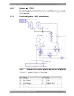
Pipe connections
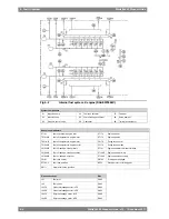
System components
Leak fuel tank, clean fuel
1T04
Day tank (MDF)
1T06
Leak fuel tank, dirty fuel
1T07
Return fuel tank
1T13
Change-over valve
1V01
Quick closing valve
1V10
If the engines are to be operated on MDF only, heating of the fuel is normally not necessary.
In such case it is sufficient to install the equipment listed below. Some of the equipment listed
below is also to be installed in the MDF part of a HFO fuel oil system.
6.3.4.1
Circulation pump, MDF (1P03)
The circulation pump maintains the pressure at the injection pumps and circulates the fuel in
the system. It is recommended to use a screw pump as circulation pump. A suction strainer
with a fineness of 0.5 mm should be installed before each pump. There must be a positive
static pressure of about 30 kPa on the suction side of the pump.
Design data:
4 x the total consumption of the connected engines and the
flush quantity of a possible automatic filter
Capacity
1.6 MPa (16 bar)
Design pressure
1.2 MPa (12 bar)
Max. total pressure (safety valve)
see chapter "Technical Data"
Nominal pressure
50°C
Design temperature
90 cSt
Viscosity for dimensioning of electric
motor
6.3.4.2
Flow meter, MDF (1I03)
If the return fuel from the engine is conducted to a return fuel tank instead of the day tank,
one consumption meter is sufficient for monitoring of the fuel consumption, provided that the
meter is installed in the feed line from the day tank (before the return fuel tank). A fuel oil cooler
is usually required with a return fuel tank.
The total resistance of the flow meter and the suction strainer must be small enough to ensure
a positive static pressure of about 30 kPa on the suction side of the circulation pump.
There should be a by-pass line around the consumption meter, which opens automatically in
case of excessive pressure drop.
6.3.4.3
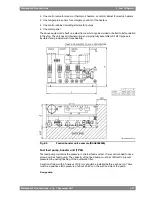
Automatic filter, MDF (1F04)
The use of an automatic back-flushing filter is recommended, normally as a duplex filter with
an insert filter as the stand-by half. The circulating pump capacity must be sufficient to prevent
pressure drop during the flushing operation.
Design data:
according to fuel specification
Fuel viscosity
50°C
Design temperature
Equal to feed/circulation pump capacity
Design flow
6-14
Wärtsilä 46F Product Guide - a19 - 1 December 2017
Wärtsilä 46F Product Guide
6. Fuel Oil System
Содержание 12V46F
Страница 1: ...PRODUCT GUIDE Wärtsilä 46F ...
Страница 44: ...This page intentionally left blank ...
Страница 52: ...This page intentionally left blank ...
Страница 78: ...This page intentionally left blank ...
Страница 102: ...This page intentionally left blank ...
Страница 124: ...This page intentionally left blank ...
Страница 144: ...This page intentionally left blank ...
Страница 162: ...This page intentionally left blank ...
Страница 186: ...This page intentionally left blank ...
Страница 192: ...This page intentionally left blank ...
Страница 194: ...This page intentionally left blank ...
Страница 197: ......
Страница 198: ......
Страница 199: ......


