
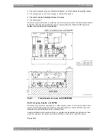


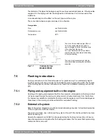


Typically lubricating oil separator units are equipped with:
●
Feed pump with suction strainer and safety valve
●
Preheater
●
Separator
●
Control cabinet
The lubricating oil separator unit may also be equipped with an intermediate sludge tank and
a sludge pump, which offers flexibility in placement of the separator since it is not necessary
to have a sludge tank directly beneath the separator.
Separator feed pump (2P03)
The feed pump must be selected to match the recommended throughput of the separator.
Normally the pump is supplied and matched to the separator by the separator manufacturer.
The lowest foreseen temperature in the system oil tank (after a long stop) must be taken into
account when dimensioning the electric motor.
Separator preheater (2E02)
The preheater is to be dimensioned according to the feed pump capacity and the temperature
in the system oil tank. When the engine is running, the temperature in the system oil tank
located in the ship's bottom is normally 65...75°C. To enable separation with a stopped engine
the heater capacity must be sufficient to maintain the required temperature without heat supply
from the engine.
Recommended oil temperature after the heater is 95°C.
It shall be considered that, while the engine is stopped in stand-by mode without LT water
circulation, the separator unit may be heating up the total amount of lubricating oil in the oil
tank to a value higher than the nominal one required at engine inlet, after lube oil cooler (see
Technical Data chapter). Higher oil temperatures at engine inlet than the nominal, may be
creating higher component wear and in worst conditions damages to the equipment and
generate alarm signal at engine start, or even a load reduction request to PMS.
The surface temperature of the heater must not exceed 150°C in order to avoid cooking of
the oil.
The heaters should be provided with safety valves and drain pipes to a leakage tank (so that
possible leakage can be detected).
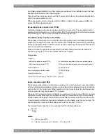
Separator (2S01)
The separators should preferably be of a type with controlled discharge of the bowl to minimize
the lubricating oil losses.
The service throughput Q [l/h] of the separator can be estimated with the formula:
where:
volume flow [l/h]
Q =
engine output [kW]
P =
5 for HFO, 4 for MDF
n =
operating time [h/day]: 24 for continuous separator operation, 23 for normal dimensioning
t =
Wärtsilä 46F Product Guide - a19 - 1 December 2017
7-7
7. Lubricating Oil System
Wärtsilä 46F Product Guide
Содержание 12V46F
Страница 1: ...PRODUCT GUIDE Wärtsilä 46F ...
Страница 44: ...This page intentionally left blank ...
Страница 52: ...This page intentionally left blank ...
Страница 78: ...This page intentionally left blank ...
Страница 102: ...This page intentionally left blank ...
Страница 124: ...This page intentionally left blank ...
Страница 144: ...This page intentionally left blank ...
Страница 162: ...This page intentionally left blank ...
Страница 186: ...This page intentionally left blank ...
Страница 192: ...This page intentionally left blank ...
Страница 194: ...This page intentionally left blank ...
Страница 197: ......
Страница 198: ......
Страница 199: ......