


temperature rise in heater [°C]
Δ
T =
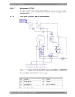
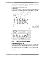
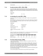
Viscosimeter, booster unit (1I02)
The heater is to be controlled by a viscosimeter. The viscosimeter should be of a design that
can withstand the pressure peaks caused by the injection pumps of the diesel engine.
Design data:
0...50 cSt
Operating range
180°C
Design temperature
4 MPa (40 bar)
Design pressure
6.3.5.5
Pump and filter unit (1N03)
When more than two engines are connected to the same feeder/booster unit, a circulation
pump (1P12) must be installed before each engine. The circulation pump (1P12) and the safety
filter (1F03) can be combined in a pump and filter unit (1N03). A safety filter is always required.
There must be a by-pass line over the pump to permit circulation of fuel through the engine
also in case the pump is stopped. The diameter of the pipe between the filter and the engine
should be the same size as between the feeder/booster unit and the pump and filter unit.
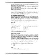
Circulation pump (1P12)
The purpose of the circulation pump is to ensure equal circulation through all engines. With
a common circulation pump for several engines, the fuel flow will be divided according to the
pressure distribution in the system (which also tends to change over time) and the control
valve on the engine has a very flat pressure versus flow curve.
In installations where MDF is fed directly from the MDF tank (1T06) to the circulation pump,
a suction strainer (1F07) with a fineness of 0.5 mm shall be installed to protect the circulation
pump. The suction strainer can be common for all circulation pumps.
Design data:
4 x the fuel consumption of the engine
Capacity
1.6 MPa (16 bar)
Design pressure
1.2 MPa (12 bar)
Max. total pressure (safety valve)
150°C
Design temperature
Pressure for dimensioning of electric motor
(
Δ
P):
1.0 MPa (10 bar)
- if MDF is fed directly from day tank
0.3 MPa (3 bar)
- if all fuel is fed through feeder/booster unit
500 cSt
Viscosity for dimensioning of electric motor
Safety filter (1F03)
The safety filter is a full flow duplex type filter with steel net. The filter should be equipped with
a heating jacket. The safety filter or pump and filter unit shall be installed as close as possible
to the engine.
Design data:
6-24
Wärtsilä 46F Product Guide - a19 - 1 December 2017
Wärtsilä 46F Product Guide
6. Fuel Oil System
Содержание 12V46F
Страница 1: ...PRODUCT GUIDE Wärtsilä 46F ...
Страница 44: ...This page intentionally left blank ...
Страница 52: ...This page intentionally left blank ...
Страница 78: ...This page intentionally left blank ...
Страница 102: ...This page intentionally left blank ...
Страница 124: ...This page intentionally left blank ...
Страница 144: ...This page intentionally left blank ...
Страница 162: ...This page intentionally left blank ...
Страница 186: ...This page intentionally left blank ...
Страница 192: ...This page intentionally left blank ...
Страница 194: ...This page intentionally left blank ...
Страница 197: ......
Страница 198: ......
Страница 199: ......