


The engine is designed for continuous operation on heavy fuel oil (HFO). On request the engine
can be built for operation exclusively on marine diesel fuel (MDF). It is however possible to
operate HFO engines on MDF intermittently without any alternations. Continuous operation
on HFO is recommended as far as possible.
If the operation of the engine is changed from HFO to continuous operation on MDF, then a
change of exhaust valves from Nimonic to Stellite is recommended.
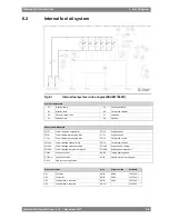
A pressure control valve in the fuel return line on the engine maintains desired pressure before
the injection pumps.
6.2.1
Leak fuel system
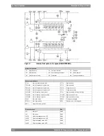
Clean leak fuel from the injection valves and the injection pumps is collected on the engine
and drained by gravity through a clean leak fuel connection. The clean leak fuel can be re-used
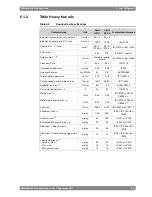
without separation. The quantity of clean leak fuel is given in chapter Technical data.
Other possible leak fuel and spilled water and oil is separately drained from the hot-box through
dirty fuel oil connections and it shall be led to a sludge tank.
6.3
External fuel oil system
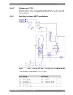
The design of the external fuel system may vary from ship to ship, but every system should
provide well cleaned fuel of correct viscosity and pressure to each engine. Temperature control
is required to maintain stable and correct viscosity of the fuel before the injection pumps (see
Technical data). Sufficient circulation through every engine connected to the same circuit must
be ensured in all operating conditions.
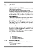
The fuel treatment system should comprise at least one settling tank and two separators.
Correct dimensioning of HFO separators is of greatest importance, and therefore the
recommendations of the separator manufacturer must be closely followed. Poorly centrifuged
fuel is harmful to the engine and a high content of water may also damage the fuel feed system.
The fuel pipe connections on the engine are smaller than the required pipe diameter on the
installation side.
Injection pumps generate pressure pulses into the fuel feed and return piping. The fuel pipes
between the feed unit and the engine must be properly clamped to rigid structures. The
distance between the fixing points should be at close distance next to the engine. See chapter
Piping design, treatment and installation.
A connection for compressed air should be provided before the engine, together with a drain
from the fuel return line to the clean leakage fuel or overflow tank. With this arrangement it is
possible to blow out fuel from the engine prior to maintenance work, to avoid spilling.
NOTE
In multiple engine installations, where several engines are connected to the same
fuel feed circuit, it must be possible to close the fuel supply and return lines
connected to the engine individually. This is a SOLAS requirement. It is further
stipulated that the means of isolation shall not affect the operation of the other
engines, and it shall be possible to close the fuel lines from a position that is not
rendered inaccessible due to fire on any of the engines.
6.3.1
Fuel heating requirements HFO
Heating is required for:
●
Bunker tanks, settling tanks, day tanks
●
Pipes (trace heating)
●
Separators
Wärtsilä 46F Product Guide - a19 - 1 December 2017
6-7
6. Fuel Oil System
Wärtsilä 46F Product Guide
Содержание 12V46F
Страница 1: ...PRODUCT GUIDE Wärtsilä 46F ...
Страница 44: ...This page intentionally left blank ...
Страница 52: ...This page intentionally left blank ...
Страница 78: ...This page intentionally left blank ...
Страница 102: ...This page intentionally left blank ...
Страница 124: ...This page intentionally left blank ...
Страница 144: ...This page intentionally left blank ...
Страница 162: ...This page intentionally left blank ...
Страница 186: ...This page intentionally left blank ...
Страница 192: ...This page intentionally left blank ...
Страница 194: ...This page intentionally left blank ...
Страница 197: ......
Страница 198: ......
Страница 199: ......