


61
W&T
Interfaces and displays
Subject to error and alteration
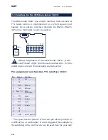
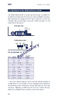
The serial TTL interface
This interface can be configured as the TTL port of a UART.
The solder jumpers must be set as follows:
• LB5, LB6 = in
• LB7, LB8, LB9 = out
The RS485 interface with automatic control
The following configuration of solder jumpers establishes a
2-wire RS485 bus connection on pins 7 and 8 of X4.
• LB5, LB6 = out
• LB7, LB8, LB9 = in
The RS485 driver ship is automatically enabled each time
data is sent and disabled (high impedance state) again when
data output is finished. The RS485 receiving channel is
deactivated when the driver is on, but is switched on when
the driver is in the high impedance state.
RS485 mode requires that the bus system be terminated with a
termination network which ensures a defined idle state in the
high impedance phases of bus mode. If the bus system in
question does not already have a termination, one can be set
using (inserting) jumpers J3 and J4.
1
The serial TTL interface and the RS485 bus can be
used only in alternation.
Preliminary
Содержание 58031
Страница 8: ...W T ...
Страница 38: ...38 W T Form factors ...
Страница 102: ...102 W T The protocol stack of the Com Server ...
Страница 128: ...128 W T The Windows COM redirector ...
Страница 134: ...134 W T Box to Box mode ...
Страница 152: ...152 W T Data transfer per Telnet ...
Страница 192: ...192 W T Firmware update of the Com Server ...
Страница 215: ...215 W T Appendix Subject to error and alteration Declaration of conformity ...


