53
5.3 Dimensions, output values, flue gas values
All information provided by the exhaust gas values are based on the EN 12815 under stationary labo-
ratory conditions reserve the right to make changes which relate to technical advances and / or to an
improvement in quality. We accept no liability for printing errors and changes which occur after printing
Model
K158 / K158F
Registration
CE, 15a B-VG, VKF
External dimensions W x H x D (without lid)
See dimensional drawing 5.4
Height with top lids open
Height with top lids closed
Fire box W x D
234 x 421 mm
Fire box height min / max
270 / 400 mm
Hearth plate W x D
442 x 542 mm
Heating door opening W x H
173 x 195 mm
Forward and return connection
each 1" back
Flue gas connection
150 mm ø
Water content in heating pocket
16 l
Operating pressure max
2.5 bar
Waterside pressure loss in heat pocket at a flow of
0.85 m
3
/h:
1.7 m
3
/h:
3 mbar
13 mbar
Required delivery pressure at NHL
12 Pa
Flue gas temperature at flue gas connection at NHL
210 / 240 °C
Flue gas mass flow at NHL wood / brown coal
31,3 / 39,7 g/sec
Room heat capacity with coal for the room with favourable,
less favourable and unfavourable heating conditions ac-
cording to DIN 18893 / Tab. 2.
Continuous heating
Timed heating
210 / 120 / 82 m
3
144 / 84 / 58 m
3
Operating temperature at regulator setting 1 / 2 / 3
45 / 60 / 80 °C
Weight gross / net
175 / 164 kg
CO (13% O
2
)
≤ 0,11 %
Dust (13% O
2
)
≤ 40 mg/m³
Efficiency
≥ 80%
Содержание K158
Страница 4: ...4 Geräteaufbau 1 9 2 6 4 8 7 13 5 3 10 12 11 K158F K158 ...
Страница 25: ...25 Bild 8 Bild 7 Bild 9 Bild 10 a b Bild 11 ...
Страница 26: ...26 Bild 12 Bild 13 Bild 14 Bild 15 Bild 16 Bild 17 ...
Страница 27: ...27 Bild 19 Bild 18 Bild 20 ...
Страница 29: ...29 Bild 29 Bild 30 Bild 33 Bild 31 Bild 32 Bild 35 Bild 36 Bild 34 ...
Страница 32: ...32 ...
Страница 33: ...33 ...
Страница 34: ...34 ...
Страница 37: ...37 Assembly K158 1 9 2 6 4 8 7 13 5 3 10 12 11 K158F ...
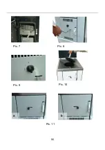
Страница 56: ...56 Pic 8 Pic 7 Pic 9 Pic 10 a b Pic 11 ...
Страница 57: ...____________________________________________________________ 57 Pic 12 Pic 13 Pic 14 Pic 15 Pic 16 Pic 17 ...
Страница 58: ...____________________________________________________________ 58 Pic 19 Pic 18 Pic 20 ...
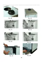
Страница 59: ...59 Pic 23 Pic 24 Pic 25 Pic 26 Pic 27 Pic 28 ...
Страница 65: ...65 Structure de l appareil K158 K158F 1 9 2 6 4 8 7 13 5 3 10 12 11 ...
Страница 81: ...81 fig 8 fig 7 fig 9 fig 10 a b fig 11 ...
Страница 82: ...82 fig 12 fig 13 fig 14 fig 15 fig 16 fig 17 ...
Страница 83: ...83 fig 19 fig 18 fig 20 ...
Страница 84: ...84 fig 23 fig 24 fig 25 fig 26 fig 27 fig 28 ...
Страница 85: ...85 fig 30 fig 35 fig 36 fig 34 fig 29 fig 33 fig 31 fig 32 ...
Страница 90: ...90 Struttura dell apparecchio K158 K158F 1 9 2 6 4 8 7 13 5 3 10 12 11 ...
Страница 111: ...111 fig 8 fig 7 fig 9 fig 10 a b fig 11 ...
Страница 112: ...112 fig 12 fig 13 fig 14 fig 15 fig 16 fig 17 ...
Страница 113: ...113 fig 19 fig 18 fig 20 ...
Страница 114: ...114 fig 23 fig 24 fig 25 fig 26 fig 27 fig 28 ...
Страница 115: ...115 fig 33 fig 35 fig 36 fig 34 fig 29 fig 30 fig 31 fig 32 ...
Страница 118: ......
Страница 119: ...119 ...


