


48
4. INSTRUCTIONS
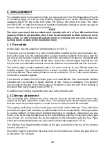
4.1 General information
The following directions and instructions concern questions of fundamental importance. It
is further presupposed that the installer of a heating plant has the necessary technical and
craftsman's basic knowledge for the task. This is naturally also the assumption where the
stove is being incorporated as an integrated stove into an existing system.
Heating stoves with heat exchangers are only suitable for closed systems with a heat sink.
Stoves without heat exchangers should be used with a heat sink.
The regulations according to EN 12828, EN 12831 and EN 12897 apply.
We do however recommend using the external heat sink in conjunction with a domestic
water boiler even for open systems, to control the stove's boiling function when there is a is
a limited heating requirement of hot water.
4.2 Important Notes
The heating stove must be put in place using a spirit level to ensure correct adjustment.
Threaded pipe connectors, straight or angled, should be used to for the flow and return
connections. Sleeves fittings or welding should not be used.
Horizontal pipe exits from the heating stove are to be in 1"-diameter. Reductions can only
be made in vertical connections.
The filling and emptying cock should always be located at the lowest point of the system in
the return connection.
Up to a static height of 10 m, the capacity pressure expansion vessel is dependent on the
water capacity of the system as follows:
Water content
Vessel size
Litre
Litre
up to 111
12
112 - 167
18
168 - 231
25
232 - 324
35
325 - 463 50
464 - 741
80
There should no manually operable shut off valves installed between the expansion vessel
and the stove.
A ventilation section at least 0.5 m above the highest circulation point in closed systems
with a diameter of at least 1
″
should be arranged and a ventilation valve provided at the
upper end.
In gravity systems the rise and fall of horizontal pipes should be at least 0.5 cm/m.
Radiators with more than 25 ribs or plate heat exchangers over 1.5 m long should be di-
agonally connected to the flow and return pipes.
Содержание K158
Страница 4: ...4 Geräteaufbau 1 9 2 6 4 8 7 13 5 3 10 12 11 K158F K158 ...
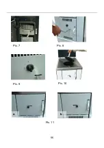
Страница 25: ...25 Bild 8 Bild 7 Bild 9 Bild 10 a b Bild 11 ...
Страница 26: ...26 Bild 12 Bild 13 Bild 14 Bild 15 Bild 16 Bild 17 ...
Страница 27: ...27 Bild 19 Bild 18 Bild 20 ...
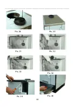
Страница 29: ...29 Bild 29 Bild 30 Bild 33 Bild 31 Bild 32 Bild 35 Bild 36 Bild 34 ...
Страница 32: ...32 ...
Страница 33: ...33 ...
Страница 34: ...34 ...
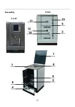
Страница 37: ...37 Assembly K158 1 9 2 6 4 8 7 13 5 3 10 12 11 K158F ...
Страница 56: ...56 Pic 8 Pic 7 Pic 9 Pic 10 a b Pic 11 ...
Страница 57: ...____________________________________________________________ 57 Pic 12 Pic 13 Pic 14 Pic 15 Pic 16 Pic 17 ...
Страница 58: ...____________________________________________________________ 58 Pic 19 Pic 18 Pic 20 ...
Страница 59: ...59 Pic 23 Pic 24 Pic 25 Pic 26 Pic 27 Pic 28 ...
Страница 65: ...65 Structure de l appareil K158 K158F 1 9 2 6 4 8 7 13 5 3 10 12 11 ...
Страница 81: ...81 fig 8 fig 7 fig 9 fig 10 a b fig 11 ...
Страница 82: ...82 fig 12 fig 13 fig 14 fig 15 fig 16 fig 17 ...
Страница 83: ...83 fig 19 fig 18 fig 20 ...
Страница 84: ...84 fig 23 fig 24 fig 25 fig 26 fig 27 fig 28 ...
Страница 85: ...85 fig 30 fig 35 fig 36 fig 34 fig 29 fig 33 fig 31 fig 32 ...
Страница 90: ...90 Struttura dell apparecchio K158 K158F 1 9 2 6 4 8 7 13 5 3 10 12 11 ...
Страница 111: ...111 fig 8 fig 7 fig 9 fig 10 a b fig 11 ...
Страница 112: ...112 fig 12 fig 13 fig 14 fig 15 fig 16 fig 17 ...
Страница 113: ...113 fig 19 fig 18 fig 20 ...
Страница 114: ...114 fig 23 fig 24 fig 25 fig 26 fig 27 fig 28 ...
Страница 115: ...115 fig 33 fig 35 fig 36 fig 34 fig 29 fig 30 fig 31 fig 32 ...
Страница 118: ......
Страница 119: ...119 ...