


38
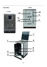
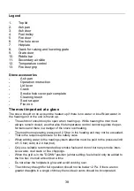
Legend
1.
Top lid
2.
Ash pan
3.
Ash door
4.
Fuel trolley
5.
Fire door
6.
Fire hole cover
7.
Hotplate
8.
Crank for raising and lowering grate
9.
Grate door
10.
Riddle bar
11.
Secondary air slide
12.
Temperature control
13.
Fire door grip
Stove accessories
-
Ash pan
-
Operation instruction
-
Lid lever
-
Crank
-
Smoke hole cover pair complete
-
Cleaning brush
-
Soot scraper
-
Fire iron
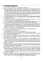
The most important at a glace
The stove should on no account be heated up if there is no water or insufficient water in
the heating unit or the unit is frozen up.
-
The ash door should only be open when heating up. While heating the door must
always remain closed, as otherwise the temperature control cannot regulate the per-
formance and there is a danger of the stove overheating.
-
The maximum operating pressure of 2.5 bar in the heating unit may not be exceeded.
That is the response pressure for the safety valve.
-
When adding water to the heating system attention must be paid to the pressure limit
of 1.5 bar (cold) or 2.0 bar (hot).
-
Only use suitable recommended low smoke fuels and do not burn any smoke inten-
sive waste, coal slack or fine chippings.
-
When the grid is in the "DOWN" position (winter setting) fuel should only be added to
the fire box in small amounts at a time.
-
Do not allow the hotplate to glow and avoid cooking over.
-
The chimney draught for full operation should not be below 12 Pa. If there are too
greater draughts in a single chimney then side air vents should be incorporated.
Содержание K158
Страница 4: ...4 Geräteaufbau 1 9 2 6 4 8 7 13 5 3 10 12 11 K158F K158 ...
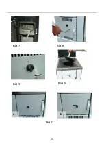
Страница 25: ...25 Bild 8 Bild 7 Bild 9 Bild 10 a b Bild 11 ...
Страница 26: ...26 Bild 12 Bild 13 Bild 14 Bild 15 Bild 16 Bild 17 ...
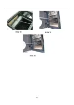
Страница 27: ...27 Bild 19 Bild 18 Bild 20 ...
Страница 29: ...29 Bild 29 Bild 30 Bild 33 Bild 31 Bild 32 Bild 35 Bild 36 Bild 34 ...
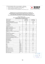
Страница 32: ...32 ...
Страница 33: ...33 ...
Страница 34: ...34 ...
Страница 37: ...37 Assembly K158 1 9 2 6 4 8 7 13 5 3 10 12 11 K158F ...
Страница 56: ...56 Pic 8 Pic 7 Pic 9 Pic 10 a b Pic 11 ...
Страница 57: ...____________________________________________________________ 57 Pic 12 Pic 13 Pic 14 Pic 15 Pic 16 Pic 17 ...
Страница 58: ...____________________________________________________________ 58 Pic 19 Pic 18 Pic 20 ...
Страница 59: ...59 Pic 23 Pic 24 Pic 25 Pic 26 Pic 27 Pic 28 ...
Страница 65: ...65 Structure de l appareil K158 K158F 1 9 2 6 4 8 7 13 5 3 10 12 11 ...
Страница 81: ...81 fig 8 fig 7 fig 9 fig 10 a b fig 11 ...
Страница 82: ...82 fig 12 fig 13 fig 14 fig 15 fig 16 fig 17 ...
Страница 83: ...83 fig 19 fig 18 fig 20 ...
Страница 84: ...84 fig 23 fig 24 fig 25 fig 26 fig 27 fig 28 ...
Страница 85: ...85 fig 30 fig 35 fig 36 fig 34 fig 29 fig 33 fig 31 fig 32 ...
Страница 90: ...90 Struttura dell apparecchio K158 K158F 1 9 2 6 4 8 7 13 5 3 10 12 11 ...
Страница 111: ...111 fig 8 fig 7 fig 9 fig 10 a b fig 11 ...
Страница 112: ...112 fig 12 fig 13 fig 14 fig 15 fig 16 fig 17 ...
Страница 113: ...113 fig 19 fig 18 fig 20 ...
Страница 114: ...114 fig 23 fig 24 fig 25 fig 26 fig 27 fig 28 ...
Страница 115: ...115 fig 33 fig 35 fig 36 fig 34 fig 29 fig 30 fig 31 fig 32 ...
Страница 118: ......
Страница 119: ...119 ...


