


WAGO-I/O-SYSTEM 750
I/O Modules 359
750-880, 750-880/025-000 ETHERNET Programmable Fieldbus Controller
Manual
Version 1.0.1
Output Process Image
Byte Destination
Instance
High Byte
Low Byte
Description
C1
C0
Control byte C1 Control byte C0
D1 D0
Setpoint position
Setpoint position
(LSB)
n
D3 D2
Setpoint position
(MSB)
Setpoint position
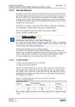
The specialty modules represent 1x6 bytes input and output data and seize 1
Instance in Class (0x67) and 1 Instance in Class (0x68).
13.3.5.9 Steppercontroller
750-670
The Steppercontroller RS422 / 24 V / 20 mA 750-670 provides the fieldbus
coupler 12 bytes input and output process image via 1 logical channel. The data to
be sent and received are stored in up to 7 output bytes (D0 … D6) and 7 input
bytes (D0 … D6), depending on the operating mode.
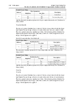
Output byte D0 and input byte D0 are reserved and have no function assigned.
One I/O module control and status byte (C0, S0) and 3 application control and
status bytes (C1 ... C3, S1 ... S3) provide the control of the data flow.
Switching between the two process images is conducted through bit 5 in the
control byte (C0 (C0.5). Activation of the mailbox is acknowledged by bit 5 of the
status byte S0 (S0.5).
Table 401: Steppercontroller RS 422 / 24 V / 20 mA 750-670
Input Process Image
Byte Destination
Instance
High Byte
Low Byte
Description
reserved S0
reserved
Status
byte
S0
D1 D0
D3 D2
D5 D4
Process data*) / Mailbox**)
S3 D6
Status byte S3
Process data*) /
reserved**)
n
S1 S2
Status
byte
S1 Status
byte
S2
*)
Cyclic process image (Mailbox disabled)
**)
Mailbox process image (Mailbox activated)


