


348 I/O Modules
WAGO-I/O-SYSTEM 750
750-880, 750-880/025-000 ETHERNET Programmable Fieldbus Controller
Manual
Version 1.0.1
Pos: 117.4 /Serie 750 (WAGO-I/O-SYSTEM)/Prozessabbild Mapping/ETHERNET - EtherNet/IP - MODBUS/TCP/PA ETHERNET - EtherNet/IP ab AIs-Rest (750-341/-841) @ 5\mod_1253705986108_21.doc @ 42060 @ 344434434444444444444444 @ 1
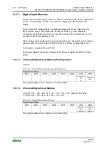
13.3.3 Analog Input Modules
The hardware of an analog input module has 16 bits of measured analog data per
channel and 8 bits of control/status.
However, the coupler/controller with EtherNet/IP does not have access to the 8
control/status bits.
Therefore, the coupler/controller with MODBUS/TCP can only access the 16 bits
of analog data per channel, which are grouped as words and mapped in Intel
format in the Input Process Image.
When digital input modules are also present in the node, the analog input data is
always mapped into the Input Process Image in front of the digital data.
Each input channel seizes one Instance in the Analog Input Point Object (Class
0x67).
Note
Information for the control/status byte development
Please refer to the corresponding description of the I/O modules for the structure
of the control/status bytes. You can find a manual with the relevant I/O module
description on the WAGO hom
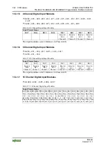
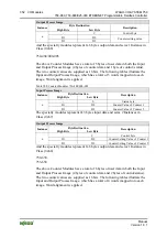
13.3.3.1 1 Channel Analog Input Modules
750-491, (and all variations)
Table 382: 1 Channel Analog Input Modules
Input Process Image
Byte Destination
Instance
High Byte
Low Byte
Description
n D1
D0
Measured
Value
U
D
n+1 D3
D2
Measured
Value
U
ref
The input modules represent 2x2 bytes and seize 2 Instances in Class (0x67).


