background image


49 

vwr.com      I Instruction manual VWR® U Water System


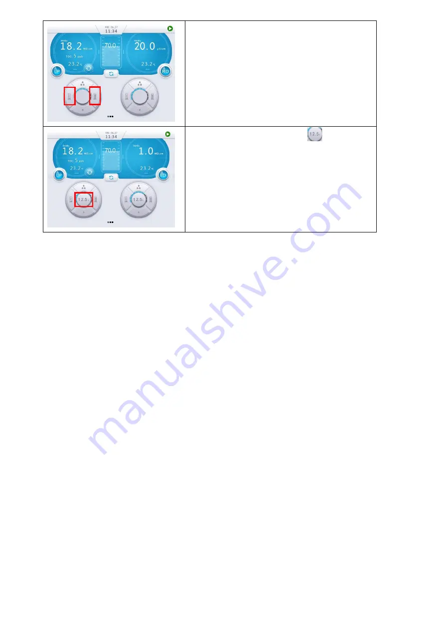
Tap the right cylinder icon to increase or the left 

cylinder icon to decrease the volume.   

You can set the volume between 0.1 and 99.9 

liters. 


Tap the middle dispensing icon


to start 

dispensing.


Volume dispensed is displayed on the 

start button position.


Volumetric dispensing will 

stop automatically after completion. 


Содержание 171-1097

Страница 1: ...UCTION MANUAL European Catalogue Numbers 171 1097 VWR U12 Water System 171 1098 VWR U12 Water System with TOC 171 1099 VWR U24 Water System 171 1244 VWR U24 Water System with TOC 171 1245 VWR U32 Wate...

Страница 2: ...of Manufacturer Europe VWR International bv Researchpark Haasrode 2020 Geldenaaksebaan 464 B 3001 Leuven 32 16 385011 be vwr com UK Importer VWR International Ltd Hunter Boulevard Magna Park Lutterwo...

Страница 3: ...Measurements 2 4 Installation 3 SYSTEM STARTUP AND OPERATION 3 1 Check List Prior to System Startup 3 2 System Initial Startup 3 3 System Setting up 3 4 Information Menu 3 5 Maintenance Menu 4 DISPEN...

Страница 4: ...oroughly for its instructions on installation use and maintenance Proper installation use and maintenance guarantee the continuous flow of high quality ultrapure water Please contact us or your local...

Страница 5: ...connections 5 Water outlets 6 Wall mount ports 7 Touchscreen 8 Final filter 9 Crossbar 10 Crossbar release button 11 Center post 12 Dispenser base 13 Finger rest hook 14 Corrugated tubing 15 Cable and...

Страница 6: ...bution of ultrapure water and RO water from tap water It consists of three main units Main System manages the production of ultrapure water and RO water Dispenser integrates the touchscreen and manage...

Страница 7: ...mp reduces TOC level in ultrapure water On line TOC monitor is based on complete oxidation method to obtain more accurate measurement of the TOC Various final filters optional can ensure ultrapure wat...

Страница 8: ...lications HPLC High Performance Liquid Chromatography mobile phase preparation Preparation of reagent blank solution As sample diluents for GC HPLC AA ICP MS and other analytical techniques Preparatio...

Страница 9: ...0 2 m final filter or Bio filter Microorganism 0 01 cfu mL with a 0 2 m final filter or Bio filter Pyrogen Content 0 001 EU mL with Bio filter RNases 0 5 pg mL with Bio filter DNases 10 pg mL with Bio...

Страница 10: ...ter then through a polishing cartridge to remove the last trace of ions then a 0 2 m final filter to the outlet VWR U Water Flow Diagram No Description No Description C1 RO Booster Pump C2 Distributio...

Страница 11: ...B RO 1 199 S cm Channel C UP 1 18 2 M cm Channel D HP 1 18 2 M cm Pressure Range 0 1 6 MPa Flow Meter Range 1 30 L min Temperature Range 0 100 o C Tank Level 0 2 m Continuous display or 0 3 m submersi...

Страница 12: ...above 6 0 bar needs to install an external pressure regulator Conductivity at 25 C 2000 S cm pH 4 10 Water temperature 5 45 o C Total dissolved solids TDS 1000 ppm Total Organic Carbon TOC 2000 ppb Ha...

Страница 13: ...em Structure and Flow Diagrams 2 4 2 1 Main System Back Side View Illustration of water inlets and outlets No Label Description Tubing Diameter Connect to A HP Dispenser A For pure water 8 mm Dispense...

Страница 14: ...e booster pump control line Booster pump optional 4 Power Power cord port Power adapter 5 Prefilter Sensor For backwash signal line Prefiltration optional 6 Overflow Sensor For overflow sensor signal...

Страница 15: ...15 vwr com I Instruction manual VWR U Water System 2 4 2 2 VWR U External Connection Diagram Red Line Electrical loop Blue Line Water loop Level sensor Tap water Power supply Feed valve Leak sensor...

Страница 16: ...76 Operating voltage 24 V DC 3 3 m to solenoid valve Fitting 1 2 female BSP Inlet 8 mm quick connector Outlet Method of water leak detection Conductivity Put the sensor near the water system Operating...

Страница 17: ...tubing into the inlet of prefiltration device and the other end into the outlet of the feed valve c Similarly cut another appropriate length of 8 mm PE tubing Insert one end of the tubing into the por...

Страница 18: ...No Description Connect to A 8 mm tubing port Main system B 8 mm tubing port Main system C Data cable port Main system or power D Data cable port Main system or power E Foot switch port Foot switch Op...

Страница 19: ...the crossbar on the center post place the dispenser handle on the magnetic base of the dispenser arm c Take the tubing bundle out from the package including two pieces of tubing and a cable Install t...

Страница 20: ...Dispense button 3 Dispenser tubing connector Main system 4 Dispenser cable connector Main system Package No Name Quantity Note 1 Dispenser 1 2 Base kit 1 Including screws 3 Accessories bag 1 One dispe...

Страница 21: ...base b Open the side panels of the main system on both sides Remove the screws as shown below c Remove the corresponding cap from the crossbar Remove the fixed block from the cap d Insert the holding...

Страница 22: ...penser Insert the dispenser tubing connectors into the HP Dispenser A port and HP Dispenser B port on the back of the Genie main system respectively Then insert the dispenser cable connector into the...

Страница 23: ...scribed above d Connect the tubing and the power adapter as shown in the pictures below Take the tubing out from the package cut two pieces in proper length and insert them to the system and dispenser...

Страница 24: ...e dispenser The kit comes with a 10 meter link bundle and a power adapter b Assemble the dispenser as that described above c Connect the tubing and power adapter as shown in the pictures below Take th...

Страница 25: ...Included Package Item Description No 1 Tank 1 2 Faucet accessories bag 1 3 8 mm elbow plug 3 4 quick connector 1 5 3 m PE tubing 1 6 UV sanitization module 1 7 Quick installation guide 1 2 4 5 2 Inst...

Страница 26: ...e first 8 mm tubing into the INLET port at the top of the PE tank and the other end into the Product To Tank on the system e Insert one end of the second 8 mm tubing into the OUTLET at the base of the...

Страница 27: ...hole in the middle of the controller Then carefully insert the UV lamp completely into the chamber Hold the UV lamp and connect it to the UV lamp base Screw the sealing cap to the UV lamp mounting hol...

Страница 28: ...Tap Water In Connect the other end to the tap water Gently pull the tubing outwards to check if the connection is secure c Insert one end of the second 8 mm PE tubing into the RO Drain on the system C...

Страница 29: ...r meets minimal requirements Check List Feed water quality Municipal water TDS 1000 ppm Conductivity 2000 S cm at 25 C Water temperature 5 45 o C Pressure 15 90 psi 1 6 bar Feed water connected Leak p...

Страница 30: ...er up in a few seconds 3 2 1 Language Setup The language setup menu will show up in the first page Default is English You may choose the language desired and then tap Next to set up Time Date 3 2 2 Ti...

Страница 31: ...sure In Bar Default sensor form VWR is 0 2 bar 3 2 4 Other Devices Setup Put in the box of Printer if a printer is used Put in the box of Bio filter if a Bio filter is installed Put in the box of 0 2...

Страница 32: ...32 vwr com I Instruction manual VWR U Water System 3 2 5 Connectivity Setup Select Wireless if wireless dispenser is opted Check in the red box Tap Next to enter consumables installation interface...

Страница 33: ...Details are shown below Note 1 RFID tags are either inside consumable packages or for preinstalled UV lamps etc inside USB key package 2 For traceability your User Name is required to install register...

Страница 34: ...rtridge installation is illustrated below a Remove the right side panel from the system as shown below b Take out the cartridges from their packaging respectively Remove caps on the cartridge s inlet...

Страница 35: ...low tap Install to complete the installation Follow the same procedure to install other cartridges Install the AC Pack the P pack and the T Pack Optional cartridge to the left side of the system the R...

Страница 36: ...sers may have prior registered to other systems causing problems in installation if record in the dispenser is not cleared Press Query will clear such record Tap Reset system will automatically reset...

Страница 37: ...wr com I Instruction manual VWR U Water System Tap Save to save the configuration Confirm the configuration by tap Finish System will enter the home screen automatically Now the system is ready to ope...

Страница 38: ...system starts up for the first time System will enter into production mode after flushing The system automatically detects the quality of the RO water discharges it to the drain if it doesn t meet qua...

Страница 39: ...sing Screw off the adapter 3 3 4 Installing the Final Filter a Open the attached final filter package b Screw the final filter onto the remote dispenser until finger tight no leak at dispensing Do not...

Страница 40: ...ality temperature and operation mode Section 5 UP water dispensing set up Volumetric dispensing button decrease the volume down to 0 1 L Volumetric dispensing button increase the volume up to 99 9 L D...

Страница 41: ...Water quality parameters UP dispenser displays water resistivity TOC and temperature RO dispenser displays water conductivity and temperature Section 3 Dispensing set up Recirculation button Volumetr...

Страница 42: ...re monitored UP TOC and Temp UP water resistivity TOC and temperature are monitored Feed and Disp Rate Feed water flow rate and UP water dispense rate are monitored Consumables Status Displays details...

Страница 43: ...d alarms stop the system from operating to protect the system Alerts appear when a consumable needs to be replaced or a non critical event occurs About Including catalog number serial number productio...

Страница 44: ...word in the popup and click login to do the operation The initial manager user name is manager please refer to the password txt file in the USB flash drive for the password Select Language no password...

Страница 45: ...ration The calibration menu is used to calibrate water dispense rate from the dispenser LCD Change screen brightness and choose energy saving if needed Set the time for screensaver Final Filter Put in...

Страница 46: ...console will make beeping sounds when alarm s appear s Provide selections to open or close tank recirculation User Setup Manager can add new account to operate the system Tap Add then enter a new user...

Страница 47: ...the cleaning that is performed on the system Including Cl cleaning and pH cleaning Distribution Control For system equipped with a distribution pump tap Distribution Control to setup the distribution...

Страница 48: ...tly from the pure water tank Note Dispensers are interlocked Only one dispenser can be used at a time Other dispensers will display In Use on the dispenser 4 2 Dispensing UP Water 4 2 1 Tap recirculat...

Страница 49: ...increase or the left cylinder icon to decrease the volume You can set the volume between 0 1 and 99 9 liters Tap the middle dispensing icon to start dispensing Volume dispensed is displayed on the sta...

Страница 50: ...Installation Date XXXX XX XX It is XX days overdue Please replace it in time so as not to affect the performance of the system CAT NO 171 1255 LOT NO S6PDC0101 Exchange the P Pack and reset H Pack 300...

Страница 51: ...so as not to affect the performance of the system CAT NO 171 1270 LOT NO S6PDC0101 Exchange the tank UV lamp and reset Tank Vent Filter Installation Date XXXX XX XX It is XX days overdue Please repla...

Страница 52: ...op dispensing until water tank is refilled Tank Water Resistivity SP Pure tank water resistivity is below preset value Replace T Pack or contact a VWR professional engineer Pure Water Dispensing Resis...

Страница 53: ...neer UP Product Temperature 5 o C Contact a VWR professional engineer TOC Sensor Temperature 45 o C Contact a VWR professional engineer TOC Sensor Temperature 5 o C Contact a VWR professional engineer...

Страница 54: ...the P Pack cartridge c Install the Cleaning Pack come with each new system Need to add one chlorine pill in to the Cleaning Pack d Tap Cleaning Sanitization on Maintenance Menu on the control console...

Страница 55: ...s used to remove adherent organic substances on the RO membrane The Acid cleaning steps are as follows a Switch the system to Standby mode and remove the left side panel b Remove the P Pack cartridge...

Страница 56: ...e Tap Cleaning Sanitization on Maintenance Menu to enter setup menu f Click Start to enter cleaning process Choose Yes on the pop up dialog g System will be back to Standby mode after pH cleaning sto...

Страница 57: ...hing pure water When needed or 12 months Reduce in resistivity of ultrapure water Bio filter Removes pyrogen RNases and DNases 3 months Increased pyrogen RNases and DNases levels System administrator...

Страница 58: ...e water Install the final filter after installing the cartridge f Scan the RFID chip for the T Pack Optional on the AC Pack location Need to put system to Standby mode and remove the AC Pack first to...

Страница 59: ...chamber f Carefully insert the new UV lamp into its chamber When about 2 3 of the lamp is inserted hold the UV lamp and connect it to the ballast cable connector 4 pin connector as shown in the pictu...

Страница 60: ...he chamber Unplug the UV lamp base c Wear gloves included in the new UV lamp package Avoid direct skin contact with the quartz glass of the UV lamp Install the new UV lamp to the lamp base and then ge...

Страница 61: ...he system to Standby mode Tap the dispense button on the dispenser to dispense water Gas inside the system will be released out of the system then remove the system right side panel b Turn the lever o...

Страница 62: ...all the cartridges d Using a Phillips screwdriver remove the 5 screws on the white back panel e Find the inlet filters shown as the red circle in the left side picture below remove the blue buckles s...

Страница 63: ...d Take out the 8 mm PE tubing and connect it to the drain outlet of the tank put the other end into the drain Note Please check local regulations on how to properly discharge 0 1 M NaOH e Open the dra...

Страница 64: ...screen to Maintenance Menu in Standby mode Tap History on Maintenance Menu Tap Start Date and End Date to choose the date that need to check Tap Search to check the history data The history data inclu...

Страница 65: ...on the USB that comes with the system Insert a USB stick to the right side of the control console to export the history data as shown above Insert the USB stick to a computer Follow the steps below to...

Страница 66: ...e file folder Data from the USB stick to open it Choose the data file you wish to check and then open it Tap Operate then choose Convert The data are as shown right You can Save the data in pdf format...

Страница 67: ...k 60 Liter PE tank w continuous level sensor overflow sensor Each 171 1255 VWR P pack Pack 171 1254 VWR AC pack Pack 171 1257 VWR H Pack Pack 171 1258 VWR U pack Pack 171 1260 VWR U pack low TOC Pack...

Страница 68: ...mp 24 VDC 1 pk Each 171 1280 UP recirculation pump 24 VDC 1 pk Each Feed pump 24 VDC 1 pk Each 171 1262 Final filter 0 2 m PES final capsule filter 1 pack Each 171 1263 Bio filter Point of use filter...

Страница 69: ...t has been damaged by accident abuse misuse or misapplication or from ordinary wear and tear If the required maintenance and inspection services are not performed according to the manuals and any loca...

Страница 70: ...cling It s also your responsibility to decontaminate the equipment in case of biological chemical and or radiological contamination so as to protect from health hazards the persons involved in the dis...

Страница 71: ...nternational Ltd VWR International Northern Ireland Ltd Orion Business Campus Northwest Business Park Ballycoolin Dublin 15 Tel 353 01 88 22 222 Email sales ie vwr com Italy VWR International S r l Vi...

Отзывы: